Palo Alto

Palo Alto Site-to-Site VPN

OMG one of the best last moment for me in 2018 was last October when me and the Crew attend GITEX the world of technology in Dubai (United Arab of Emirate)

1

IT’S THE BIGGEST & BOLDEST TECH SHOW IN MENA & SOUTH ASIA

attendees from 120+ countries and global media outlets in unpacking the big conversations and latest solutions around AI, blockchain, robotics, cloud and other mega trends, as GITEX takes you on a multi-sensory experience of Future Urbanism across 21 halls with 4,000 exhibitors across 24 sectors.

and here im going to tell you my new article

So Let me tell you, in my years in network i have never implemented a Site-to-Site VPN and i mean never ever in any product wither Cisco, Juniper or Palo Alto

so i spend reading the Last Couple of days reading and study about it and Thanks to My Mentor Mr.Keith barker from CBT Nugget https://www.cbtnuggets.com/trainers/keith-barker he Got His own way to Make the most Difficult thing Easier than you can imagine.

you can find his Palo Alto video in this Link https://www.cbtnuggets.com/it-training/palo-alto-networks-firewall

So Let’s Start, i have 2 Site

One with Palo Alto VM Machine and the Second Site i have Cisco Router 2811

I put Simple IKE Phase 1 and Phase 2

IKE 1

DH Group: group1

Encryption: aes128

Authentication: sha1

Lifetime: 5 Minute (300 seconds)

IKE 2

IPSEC Protocol: ESP

DH Group: group1

Encryption: aes128

Authentication: sha1

Lifetime: 5 Minute (300 seconds)

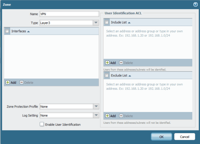
So First Create a VPN Zone Like i Show you in the First Blog

go to Network – Zones – Add new

999.png

Then create the tunnel interface

Go to Network – Interface – Select the Tunnel tab – Add new

I Choose number 1 and i have one virtual Router and Select the Zone (VPN)

1

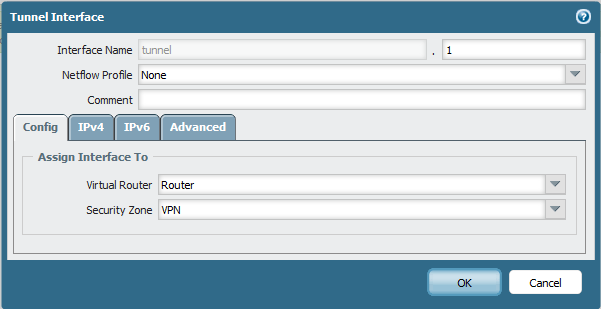
Give the Tunnel an IP Address under the IPV4 tab (10.1.1.40)2

Now Lets Create the Phase 1

go to Network – Network profile – IKE Crypto – Add new

i Configure it as my scenario

DH Group: group1

Encryption: aes128

Authentication: sha1

Lifetime: 5 Minute (300 seconds)

3

After that i create the IKE Gateway

Go to Network – Network profile – IKE Gateways – Add new

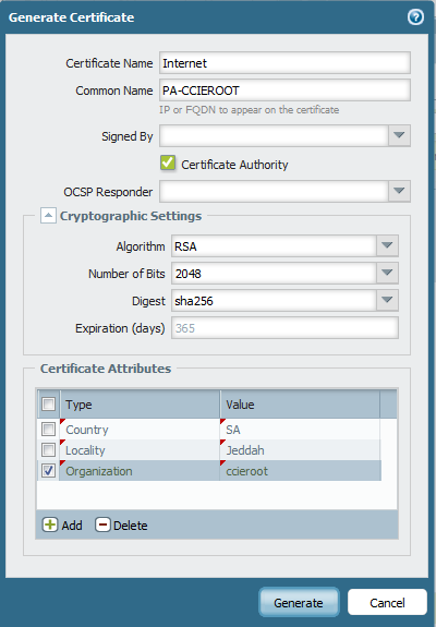
Select the WAN interface and Choose static for my Peer since  i know the IP Address and Put the Pre-shared Key (ccieroot)

4

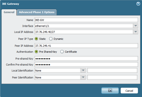
go to Advanced tab to Select the IKE Crypto profile and Choose the IKE Crypto for IKE1 i Created Earlier5

Now to IKE2 Configuration

Go to Network –  Network profile – IPSec Crypto – Add new

and Same like IKE1 we will follow out Scenario

IPSEC Protocol: ESP

DH Group: group1

Encryption: aes128

Authentication: sha1

Lifetime: 5 Minute (300 seconds)

6

After that i will Configure the IPSec Tunnel

Go to Network – IPSec tunnel – Add new

Select the Tunnel interface, IKE Gateway and IPSec Crypto profile7

Now i Create a Static Route to Site 2 LAN

Go to Network – Virtual Router – Select Our Router – Edit – Static Route Tab – Add new

type the Destination of Site2 LAN and Select your Tunnel 1 and Type Site2 Tunnel Interface IP Address as My Next hop

8

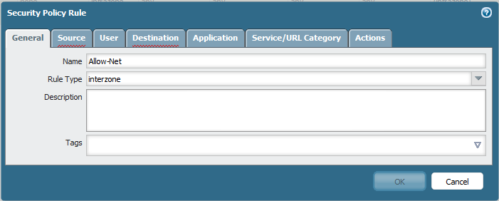
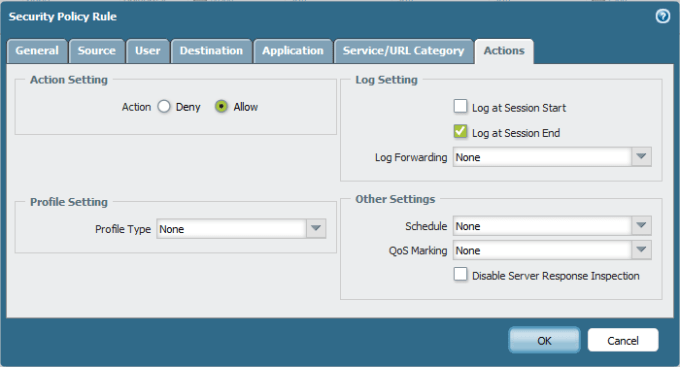
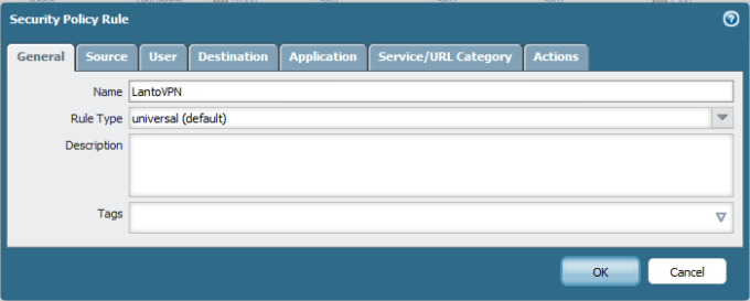
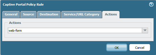
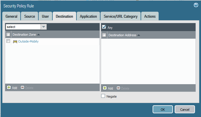
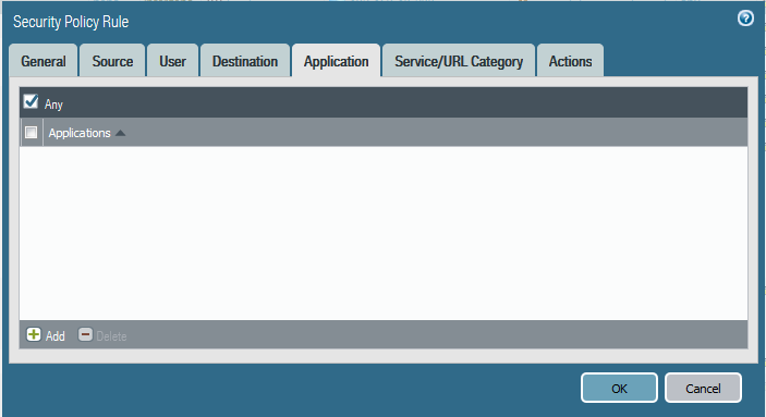
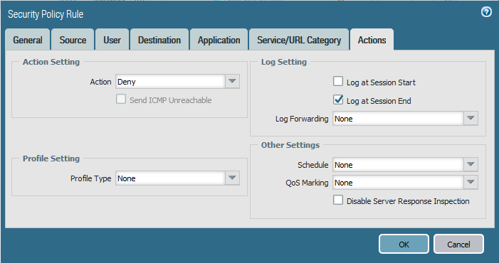
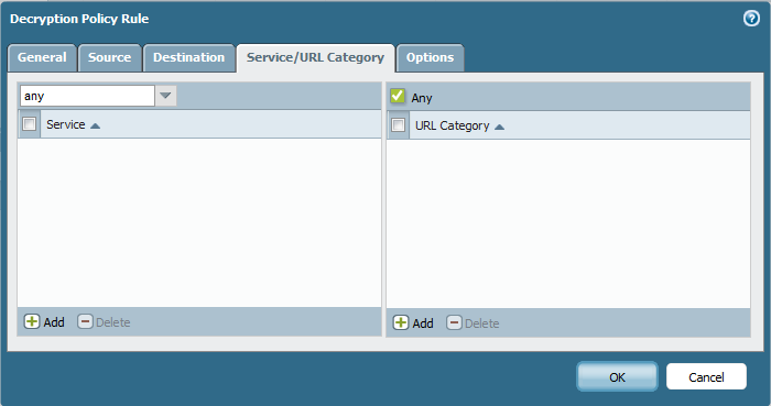
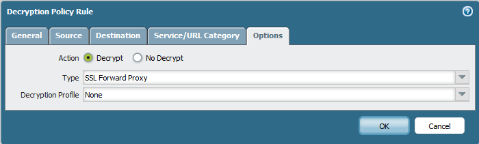
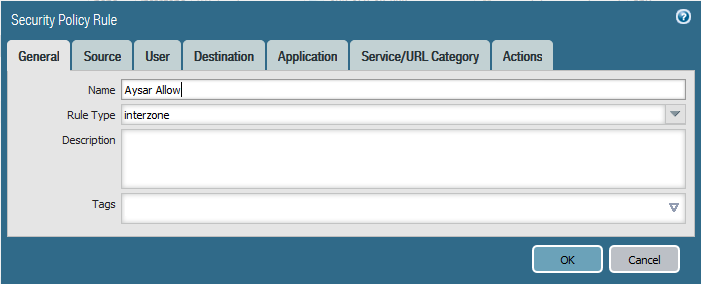
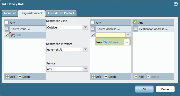
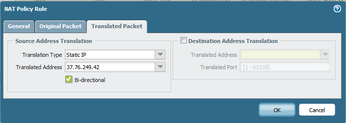
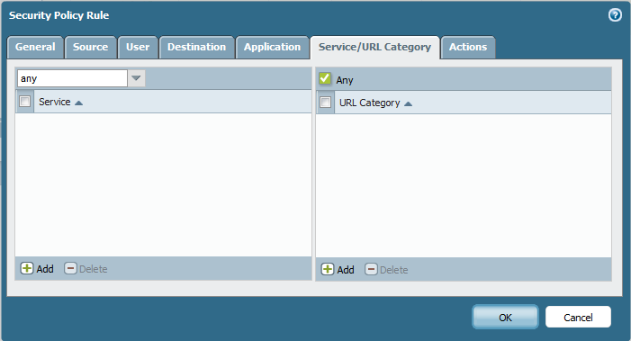
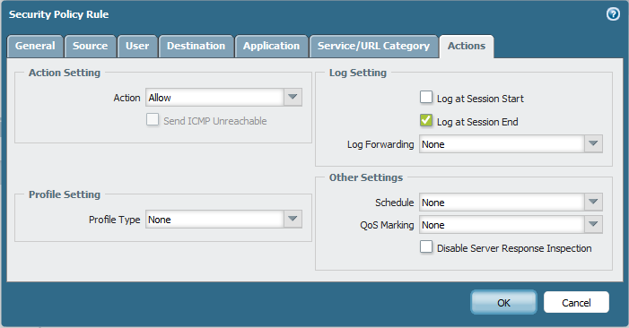
Last Part of Palo Alto is to Configure Security Policy Rule

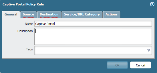
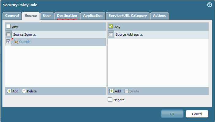
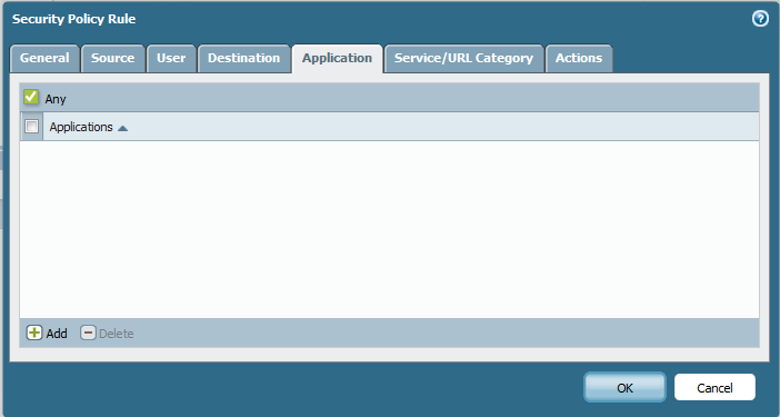
Go to Policies – Security – Add new Choose a name and Rule type Universal also Interzone could work8a

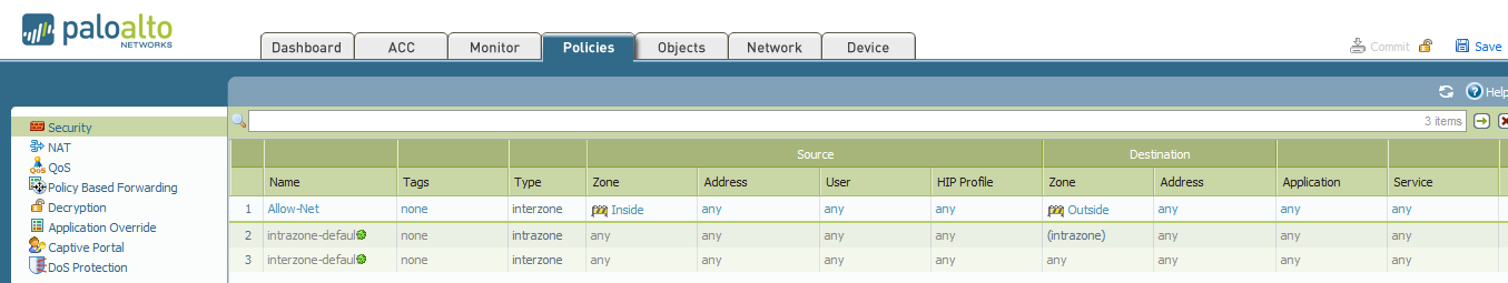
Choose Source as the Tunnel Interface Zone which was (VPN) Zone8b

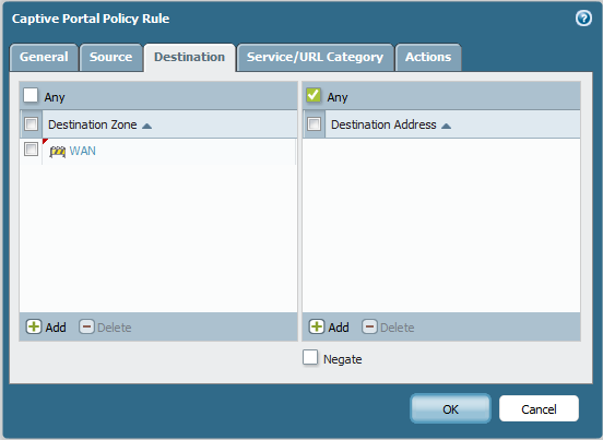
Select my Destination As (LAN) so Ping from Site2 to me Work Perfectly8c

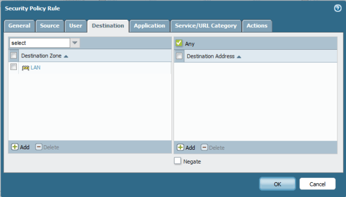
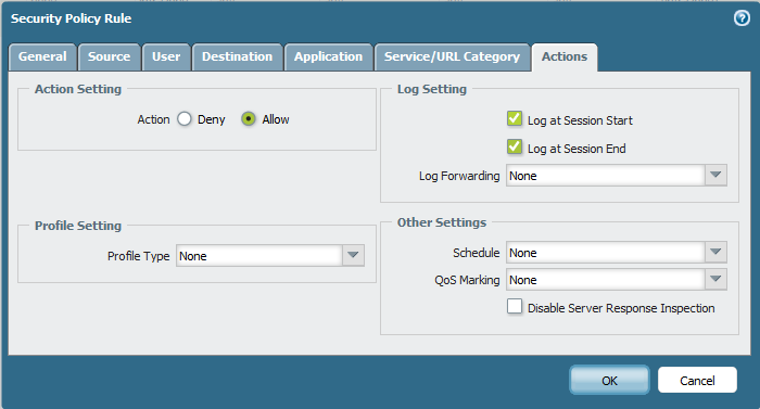
and Choose Action as Allow

22

Again do the Same to My Palo Alto user in Site1 to Allow their Ping to Reach Site2

19

Source as LAN

20

Destination As VPN21

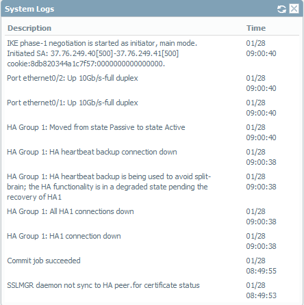
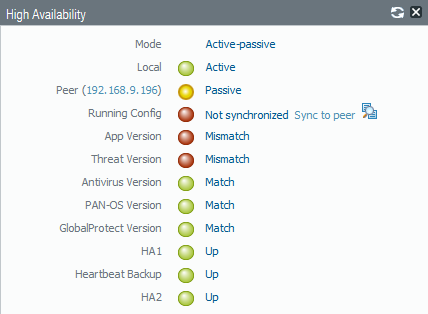
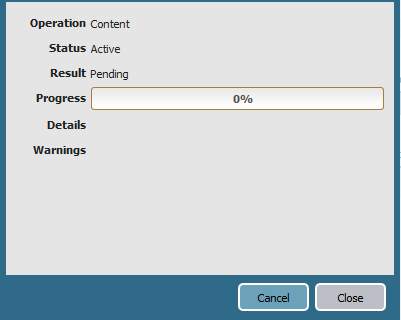
Now if you go to Network Tab – IPSec tunnel you will See the Status is (RED)9

So Lets Start now in Cisco Side To Turn that light Off

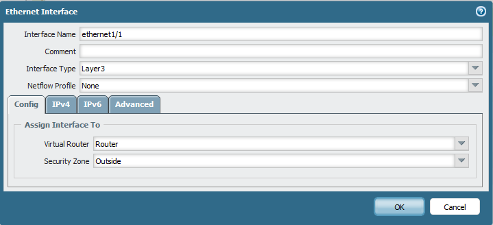
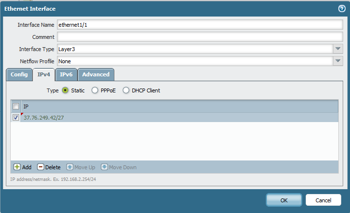
First i Configure my Public Interface which Happen to be My FastEthernet  0/0 and My Loopback which my Internal Network

10

Next i Configure my IKE Phase 1 which Same Configuration to IKE1 in Palo Alto

Dont get scare if  you show Run and you Don’t See group1 in the Configuration ;D

11

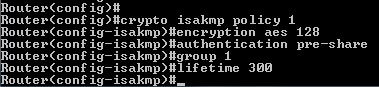
and Configure the Key Password and my Peer Address12

After that i Configure my IKE Phase 213

and Configure my IPSec Profile
14

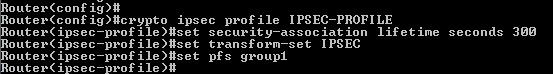
Then i Configure my Tunnel Interface
15

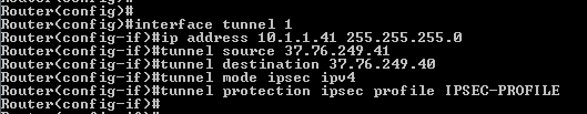
and Last but not Least i Configure my Route to Site 1 LAN16

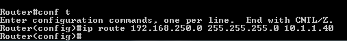
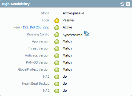
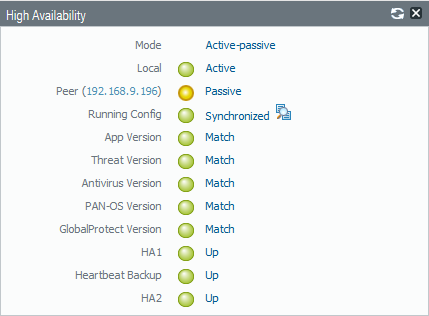
and now when i get back to my Palo Alto i see the Status turn Green17

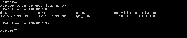
Also you can check the status on the Router

900

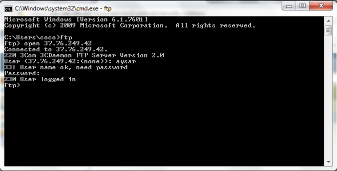
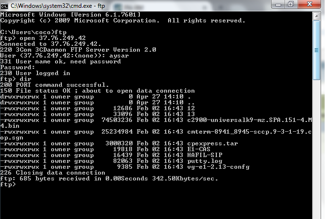
Now i ping from my Router to Palo Alto LAN Interface and it’s Work Perfectly

18

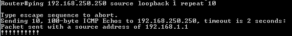
i Also Login by my PC and i Ping the loopback and ti work perfectly23

;D

Standard
Palo Alto

Palo Alto Captive Portal

Well let me tell you what happen this week
I saw one of our work mate login in his private Laptop to internet and download is so high and his user don’t show in the monitor page.

So there is a feature available in hotel and Internet Cafe and its a great feature to control who is going and coming and sometimes to which website
This Feature Called Captive portal

let me guide you in the configuration
the requirement 1, 2 & 3 available in earlier blog you can click in each component and it direct you to the page
1-LDAP
2-Authentication Profile
3-Certificate
4-Certificate Profile
5-Enable Captive Portal
6-Captive portal policies

So start from Step 4 to create a certificate profile
Go to Device – Certificate Management – Certificate profile – +
Choose Name and Select the User Domain
then under the CA Certificate Add your Cert that Created in Earlier Blog
50

60

1
Then Go to Device – User Identification – Captive Portal Settings – Edit
Make Sure to check Enable Captive Portal
Choose the Authentication Profile That we Created in the Earlier Blog
and Choose Mode Redirect
and in the Filed of Redirect Host put our LAN IP 192.168.250.250 so all traffic forward to that IP2
Now Lets Create a Captive Rule
Go to Policies – Captive Portal – +
Choose a Name
3
Then Select the Source as Inside4
Select your Destination as the Outside WAN5
After that select Your Service as HTTP and HTTPS also you can add a URL Category if you want to strict the Captive Portal to specific web sites
6
Choose the Action web-form 7
Last thing go to the Management Profile and make Sure you check the Response Pages so the user would be able to receive it
Got o Network – Network Profiles – Interface Mgmt – edit my Profile which i created in an Earlier Blog
8
Now lets go to the user PC and Open a browser to google Web Site
as you can see it direct me to 192.168.250.250 in URL
Click on Continue to this website (not recommended)
10
It will ask you for your Username and Password
I will put my LDAP Authentication Username and password20
Now it Login me30
and Walla im there40


Note: in the newer version of Palo Alto Captive Portal Policy is Called: Authentication Policy and Web-form is changed to : default-web-form

;D

Standard
Palo Alto

Blocking Youtube Using Palo Alto URL Category

Youtube
The Bandwidth Killer
to be honest i learn a lot from youtube whether cisco configuration or paloalto or even other things
but during work hour many user using youtube to hear songs, watch a movie trailer which kill the internet bandwidth so i explain earlier how to block facebook using APP-ID
but Youtube APP-ID is little diffrent cause it depend in google-base which will forbid google website too
so URL Category may save the Day
this remind me of Microsoft TMG

So first let create a URL Category
Go to Objects – Custom objects – URL Category – add new
(Youtube)
Add URL (www.youtube.com) Also you can add more (*.youtube.com)
1
now we create a security policy
Go to Policies – Security – add new (Stop Youtube)
2
Select the Source Zone (inside) and the Source Address (My Laptop IP  Address)
3
Select the user aysar.mohamed (Me)4
Select the Destination as my Outside Interface5
Select any in Application tab6
well here we go
in Service/URL Category we select the (Youtube) Category that we create earlier7
put the Action to deny8
now when i try to open Youtube i got the deny messgae ;D9
As you can see from the log i got the (Reset-both ) Action in rule of Stop youtube 10a

;D


Standard
Palo Alto

Blocking Facebook or Facebook Chat Using Palo Alto APP-ID

First i have to apologize cause this going to be a long Trip and it my fault i didn’t research it will but to deny an SSL traffic which used by facebook first you have to read what inside it, in another word (Decrypt it)

So i’m here rewrite the article again and just add the Decryption of the traffic before it forward to the intended site
First we need to create a Certificate on Firewall
Choose a name, Common name and Check the Certificate Authority
and the Certificate Attributes then Click Generate

1
Now Select the Cert to Edit and Check the Box
Forward trust Certificate
Forward Untrust Certificate
trusted Root CA
22
Then Export the Certificate as (PEM)
2
Choose Place to Save it
3
and as you see it download it in my Download Folder
4
Second i will go to my laptop to import in

Go to Tools – Internet Option – Content – Certificates
5
Go to trusted Root Certification Authorities Tab – import6
Press Next
7
Browse to my Certificate
8
Choose to place it in the Trusted Root Certification Authorities9
Press Finish
10
it will give you a security warning just press yes11
and import is successful
12
you can check it under the Trusted Root Certification Authorities Tab
13
Now get back to Palo Alto and Configure the Decryption Policies
Go to Policies – Decryption – Add14
since this is a lab i will Choose Any as the Source
15
Also Choose Any as the Destination 16
i can Adjust under URL Category but since this is a lab i will configure it as Any17
Under option Tab i select the Action as Decrypt and Type SSL Forward Proxy18
Now i Check Gmail and here its Secure from my PA-CCIEROOT which is my Palo alto Common Name20
Also my facebook is Secured 21

;D

Now that was the Part that everyone kept ask why Aysar it ain’t working
your article is wrong
will i hope it work now

So as i said earlier unless you work in Marketing then you don’t need any Social Website
so Aysar Mohamed (ME) is an IT guy and i want my self to do IT Work and stop playing around the Facebook
(i am sure my manager agree in  this point) so let’s do it

First I need to tell you when using Application you need to be careful what you choose
you can select application using Category, Subcategory, technology, Risk and Characteristics
sometimes you see if you choose based on Risk level 5 which is the hardest you could break google drive
and if you use the application using Characteristic and choose Vulnerability you could break SIP so Review everything.

Now go to Monitor – Logs – traffic and as you can see it full by Facebook logs by Aysar and it depend on one Application (facebook-base)

1
So let go to Policies – Security – add new (Stop facebook)91
Select the Source Zone (Inside) and Source Address (My Laptop IP Address)3
Select my user (Aysar.Mohamed)4
Select the Destination my outside interface5
then here choose the application (facebook-base) which appear in my logs
sometimes you need to add
(Web Browsing), (SSL) & (DNS)
90
Now Choose action to deny
92
Make sure to move this rule to the top
7
As you can see now i cant open my facebook at all and it give me this error7a
and if you go back to the logs you will see the action (reset-both)8
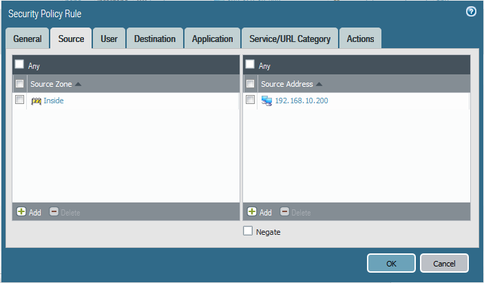
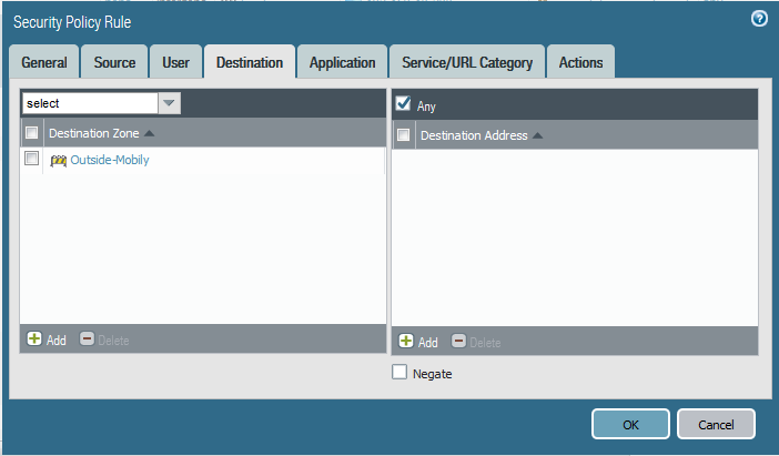
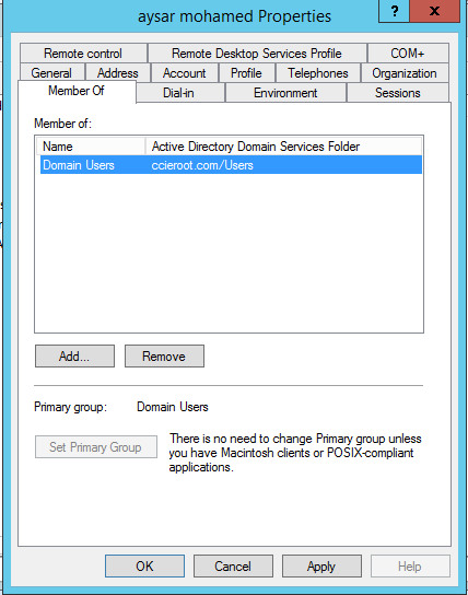
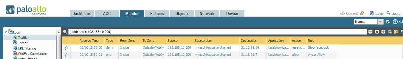
Now what if i want Aysar to view his Facebook but don’t want him to Chat with Anyone
Easy go back to my (Stop facebook) Policy change the APP-ID to (facebook-chat) and save9
some application can’t just stop by choosing the APP-ID you need to select also what it depend on
so highlight the rule and go to the application tab and choose facebook-chat and right click and choose (Value) to see what its Depends on.
so for facebook-chat it depends on
facebook-base
mqtt
Now If i select facebook-base it will also block facebook page Also
so here the trick
10
Add only mqtt
11
Then in my Second Rule (Aysar Allow) i will add to Alow the facebook-base12
under Application i will only add the facebook-base13
Now i can go to my facebook but as you can see my Chat is Dark (Unable to connect) 15
and as you can see in the Logs it block the facebook-chat14

;D
(if you need to check list of App-id you can use, go to Object tab – application)

Happy Friday Everyone

Standard
Firewall, Palo Alto, Security

Palo Alto High Availability

Down Time is not Acceptable in Any Environment
And here were the term High Availability comes to play.

To Configure the high availability in Palo Alto you need to have Two Links in each device, one for the Control Link (HA1) and one for Data Link (HA2)
both Palo Alto Device Exchange a hello message and a Heartbeat through the Control Link (HA1). if any of that not receive the Backup Palo Alto Peer will Assume that the Active Peer is Down and Take Control
(Note. this Scenario is on Active/Passive Mode)
be Aware that Both Palo Alto Device should have the Prerequisite:
1- Same model
2- Same interfaces
3- Same PAN-OS
4- License

well i’m working here on PAN-OS 7.0.1
My Active Palo Alto IP Address: 192.158.208.222
My Passive Palo Alto IP Address: 192.168.208.111

So i Show you earlier how to configure Palo Alto from scratch in the earlier Blog
Now I add extra Network card for the (HA1) & (HA2)
So to Configure the Palo Alto interface
Go to Network – Interface – Select interface
Ethernet 1/3 will represent HA1
Ethernet 1/4 will represent HA2
1

2
Now to Peer Configuration
so i Give the Active Peer IP Address
192.168.209.140 (HA1)
192.168.209.142 (HA2)
and for the Passive Peer
192.168.209.141(HA1)
192.168.209.143 (HA2)
Go to Device – High Availability – General Tab – Setup settings
Enable HA and choose a Group ID and fill the Peer IP Address and choose the mode
3
Then go to Control link (HA1 Configuration) and Choose my ethernet 1/3 as the HA1 and put the IP Address 192.168.209.140 and Netmask
4
After that i go to my Data Link (HA2) and Enable the Session for Synchronization and Put the IP Address i choose earlier 192.168.209.142 and Netmask and Gateway and for my Transport i select IP
5
Now to Election setting and to make Sure that 192.168.208.222 is the Active one i have to Put a Lower Priority
The Default is 100 so i Configure it to 90 and select Preemptive and heartbeat Backup (Heartbeat backup use the management interface which protect against Split Brain)
6.png
now go to Dashboard Tab – widgets – System – and Select HIGH Availability
so i can see the status in the Dashboard
7
and as you can see the status is so red
9
Now in the Other Peer i need to Configure the Same Interfaces for HA1 & HA2 and same configuration for HIGH Availability except the IP Addressing and for Election Setting i will just keep it the default
and then go Back to the Active Peer 192.168.208.222  and you will see the HA1 & HA2 turn to Green and now choose to Sync to Peer
10.png
It will Ask you to Overwrite Peer Configuration just Select yes
11
And now All our Configuration is Synchronized
13
Go to Passive Peer and you will See the Local Peer is the Passive
and the Active is 192.168.208.222
14
if you check the Passive Network interface you find it’s Red 15
And now to Test it i will ping  8.8.8.8 Non Stop and power off the Active Peer16
and as you can see it just took only 3 request timeout which less than 6 second and user will not notice itqqq
and if you check the System log in Dashboard you will see your passive peer notice the HA1 Control Link Went Down and the Passive become the Active
20
And our Red Interfaces Become Green21

by default link monitor enable on all links but if you want to specify the important link like Trust, Untrust and DMZ then
Go to Device - High Availability - Link and Path Monitoring - Link Group
add those interface to it
;D
Standard
Palo Alto

Plao Alto LDAP Integration (Agentless User-ID)

Active Directory Integration
In earlier Blog Palo Alto to Internet we configure how to Allow users to go to the Internet. Now Active directory allow me to control who can have an access to internet Per User and also monitor exactly whom watching who and this is the configuration

Let’s start by Microsoft Side
lets start by creating a user in the Active Directory for the mapping integration
go to Tools – Active Directory Users and Computers
9
Go to the user container and right click New – User10
i created a user aysar.mohamed@ccieroot.com
11
put the password and since this is an integration user no need to change the password and to never expire
12
Click Finish
13
go to the user settings
14
go to the member tab
the user should be Member of :
(Distribute COM User, Event Log Readers, Server Operation)
15
In Windows 2003, the service account must be given the “Audit and manage security log” user right through a group policy. Making the account a member of the Domain Administrators group provides rights for all operations. The built-in group named “Event Log Readers” is not available in Windows 2003.
Add those Group
16
Press OK
17
Second we need to check if the Domain configure to log successful logon
Open Group Policy Management
3
Then select Domains – ccieroot.com – Default Domain Policy – edit
4
go to Computer Configuration – Windows Settings – Security Settings – Local Policies – Audit Policy
Select Audit Account logon events
5
Check box Define these Policy settings
Success & Failure
6
Now it’s about time to update the policy
Go to cmd and update the policy using the command (gpupdate)7
then do the WMI Authentication part as The device uses WMI Authentication and the user must modify the CIMV2 security properties on the AD server that connects to the device.
go to cmd and input the command (wmimgmt.msc)
18
Right Click and select properties
19
go to Security Tab – Root – CIMV2 and click on Security button
20
click on Add to add the user (aysar.mohamed) that i created earlier
21

22
and give him permission:
Enable Account
Remote Enable
23

Now The Palo Alto Side
1st check the Internal Zone to have User-ID Enabled
90
Second make sure the Service route is configure to use the Inside Network for (LDAP, DNS and Kerberos)
go to Device – Setup – Service Feature – Customize
000

Next Go to Device – User Identification – Palo Alto Network user-ID Agent Setup – Click on settings button on the corner
in WMI Authentication i will use the username and password i created3
Then Enable the Server Monitoring
5
Optionally if you enable the NTLM is to discover domain you have to enable DNS configuration under
service – DNS – internal primary dns server
Also Enable the Client Probing and press ok
client probing is useful in huge environment because change will reflect on firewall immediately
every 20 minute
6
After That i will add my Active directory Under the server Monitoring
4
Then the Domain Controllers will show with a status of Connected.

First go to Device – Server Profiles – LDAP – add
Base DN: auto generate
Bind DN : (this account must be a member of the built-in Server Operators group in AD)
Also uncheck the box Require SSL/TLS secured connection
1
Then we need to create an Authentication Profile
Login Attribute: sAMAccountName
2
then Select Advanced tab and in the Allow list  select to add (All)3
Like that we done from Active Directory Integration

Now we create our group mappings so we can use these Active Directory groups in our security policies.
navigating to the Group Mapping Settings tab – Add new
5
then go to the group include list tab at the top. as long you see the OU in your AD then it mean you can see everything correctly
6
Just for testing i Add the IT Staff
7
Now on our Internet Rule Select under User tab and Add my user or group8
now as you can see under the Monitoring Tab i see my Username when i Access any website9

;D

Note:
Because WMI probing trusts data that is reported back from an endpoint, Palo Alto Network recommends that you do not use this method to obtain User-ID mapping information in a high-security network. If you configure the User-ID agent to obtain mapping information by parsing Active Directory (AD) security event logs or syslog messages, or using the XML API, Palo Alto Networks recommends you disable WMI probing.
If you do use WMI probing, do not enable it on external, untrusted interfaces.

Standard
Firewall, Palo Alto

Configure Palo Alto to allow inside DMZ (FTP server)

So DMZ
In earlier Blog Palo Alto to Internet we configure how to Allow users to go to the Internet. so today i will show you how to allow your customer to come  inside to your FTP Server
first i Configure my Ethernet 1/1 with the Public IP Address 37.76.249.42
Go to Networks – Interface – Ethernet Edit
Change type to Layer 3, Configure Virtual Router and Zone (Outside)0
Then go to IPv4 and configure an IP Address of 37.76.249.42/270a
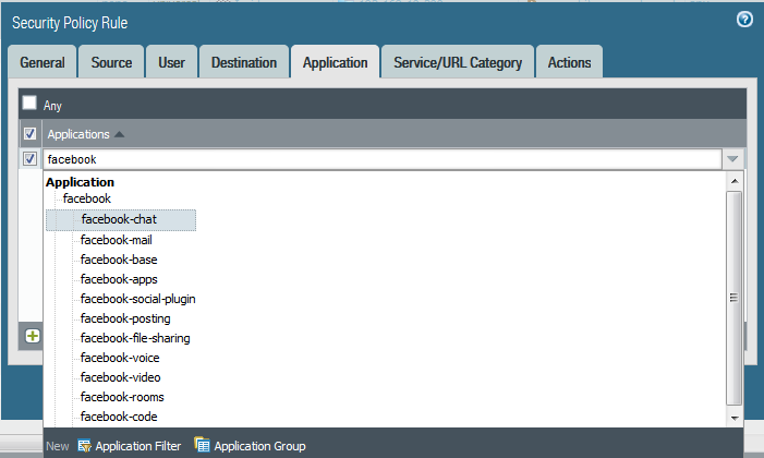
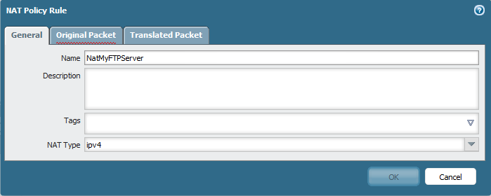
Then Configure Ethernet 1/2 for DMZ gateway
Change type to Layer 3, Configure Virtual Router and Zone (DMZ)1
Then go to IPv4 and configure an IP Address of 192.168.250.250/242
Now the most important step is to configure NAT Policy
Go to Policies – NAT – Add new
I choose name : NatMyFTPServer3
Choose your
Source Zone (DMZ)
Destination Zone (Outside)
Destination interface (Ethernet 1/1)
then i have to add my Source Address so Click on Address4
Choose a name (MyFTPServer)
Type : IP Netmask
Put the Local IP Address (192.168.250.16)5
And it’s added
and btw in case you have many Server that serve different services and only one Public IP you can adjust the services to be one for FTP, second for HTTPS and one for Remote access which consider as (Static Nat with Port Translation )
but in our case its only one server to one public ip
6
Now go to Translated Packet
Translated type: static IP
and Type the translated Address which is the public IP Address i Configure Earlier and to make sure translation go both way check  the box Bi-directional7
Now Finally let’s configure Security Policy Rule
Let me Educate you here (The Policy always is The destination Zone is Post-NAT and the Destination IP is Pre-NAT)
so you destination after the NAT is the DMZ
and your destination IP is the Pre-NAT which is your public IP Address
Confusing i know but it took me 2 years to understand it thanks to a friend of mine (Adel ;D)
Go to Policies – Security policy – Add new
Choose a Name and Rule Type as (interzone)8
Select the Source as Outside since the traffic coming from outside9
Configure the Destination as (DMZ) zone and Destination Address is your Public IP Address
10
You can custom the Application and Service/URL Category to Allow FTP Service only but since this is a Lab just select any
Select Any in Application11
Also here in case you have many Server that serve different services and only one Public IP you can adjust the services to be one for FTP, second for HTTPS and one for Remote access which consider as (Static Nat with Port Translation )
but since we have one server select Any in Service/URL Category Tab12
Then select Allow as an action for this traffic13
Now in my laptop i install 3CDaemon which a great FTP server and Choose the Upload/Download Directory in my D:\IOS\ which contain my files.
I also configure a profile (Aysar) so i can use this as my login instead of anonymous13b
And now for the BIG Test
from any Customer PC i open cmd and go to ftp to the public IP Address of the FTP Server
and as you see Authentication went well14
Just type
dir
which list all the file under my D:\IOS\15

;D

Standard
Palo Alto

Palo Alto HA Sync Issue & APP and Threat Mismatch

Just when i think everything okay a Nice View Such as Below Appear
1
I Checked All my HA Configuration and it’s Fine SO
i Define this as Two Issue
Synchronize
App and Threat Mismatch

First lets Solve the Synchronized and it’s a simple Step
Just Next to Running Config Press (Sync to Peer) so it Push the Configuration to the Passive HA
2
It will Ask you to Overwrite Peer Configuration Just press yes
3
Now it Start as you See (Synchronization in Progress)4
And as you can see now it finished and now its Synchronized 5
and now here in the Passive HA and Also show the Same 6
Now Lets Move to Next step which is the APP & Threat Mismatch
Lets Check the Version of the Application First
Go to Device – Dynamic updates – and Check the Applications and threats
7
so Go to 654-3805 which is my Latest Update also you can See in the lower of screen (Check Update)
Then Press Install on Right Side of the Application8
Check to Synch to HA Peer
press Continue Installation
9
Now it will Progress
10
And Automatically will Transfer a copy to HA Peer11
As you See now a Copy Transferred and Installed in HA Peer12
And Finally the all your HA Item in the Active Peer  is Green14

;D

Standard
Firewall, Palo Alto, Security

Palo Alto to Internet

TOP 10 Next Generation Firewalls
Palo Alto
After Spending Many Years in Cisco Security ASA and Worked with microsoft TMG the Company Decided to go to New technology
After Reading About it I realized that Gartner  agree that Palo Alto  Consider to be the leader when it comes to Next Generation Firewall appliances
So let me guide you with the First Step of Initial Setup and Configure it to Internet Access for users

Well first Let start Login to the ESXI host
1
Then Choose to Deploy the OVA File
2
Browse to my Folder were i Save the OVA3
Press Next
4
Type a Name of your Choice5
I Prefer to Select Thin Provision is i will not Reserve the Whole Size6
Select the Network7
Now Press Finish8
The Deploying Procedure Start9
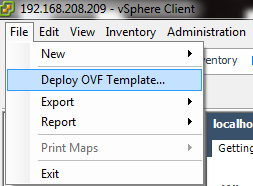
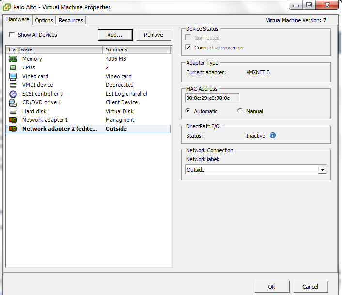
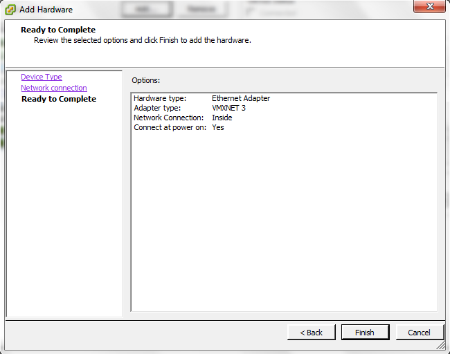
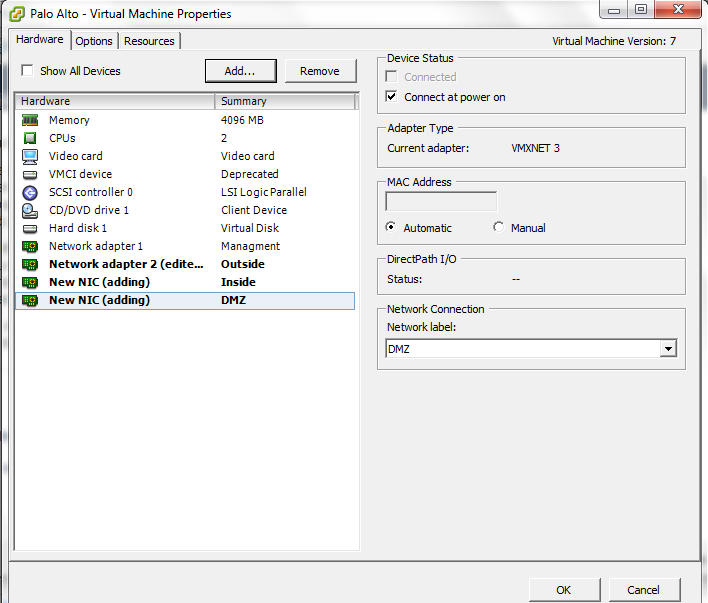
Now we Finished with The Installation of the OVA
10

Depend on your Scenario and how many Network Card you Need
in my Scenario i Need 4 (Management, WAN, LAN and DMZ)
in my ESXI i have this Already Configured as you see in the Picture

a.png
Now i will Edit My Virtual Machine
Configure the Network Adapter 2 to be my Outside
11
Click Add  and Select my Third Network Card for LAN12
Choose the Network Label (Inside) Which Represent the LAN Also DO the Same for Server Side which Represent by (DMZ)
13
Press Finish and Its Created14

15
Now Start the Machine16
Username: admin
Password:admin
and Set your IP Address for the Machine17
Now Set the Default Gateway and Save it (Commit)18
You can check your Management IP configuration by issuing the command
show interface management
Now Go to the Web Page Https://192.168.208.222
Enter the Default username and Password19
normal Warning Regard the Default username and Password20
Go to the Device – Setup – Management – Management Interface Settings and you Can Edit the Service or IP Address21
Second Go to Device – Setup – Service – Services and Configure the DNS and NTP22

23
Second Go to Network – Zones and Add the Zones (Outside, Inside and DMZ) Repeat the Same Step Below to Create Each
25

26
Now Go to Network – Virtual Router and Create New One and Name it27
Second Go to Network – Interfaces – Edit Each interface (Ethernet 1/1, 1/2 and 1/3)
Outside, inside and DMZ
Type of Layer 3
Select the virtual Router and Security Zone28
then Go to IPv4 tab and Add the IP Address29
Second go to Advanced Tab – Other info – Management profile and press new 30
Select Name and Edit the Service Permitted31
And Then Select the Management profile32
Repeat the Same Step to Each Interface (LAN and DMZ)
here the Zone is Different for inside33
and Add the LAN IP Address : 192.168.250.250
34

35
Now  Go back to Virtual Router and Add a Static Routes to Default Route to your internet ISP Router in my Case : 37.76.249.9136
Now time to Configure your Security Rule
Go to Policies – Security and Add one
Name : Allow-Net
Type: Interzone
37
Choose the Source to be Inside38
Choose the Destination: Outside39
Select the Service/ URL category : Any40
Select the Action : Allow
Log Setting Enable Log at Session Start and END41
42
Now Go to to Configure the PAT (Port Address Translation)
Policies – NAT add new
Choose Name
43
Choose your Security Zone:Inside
Destination Zone: outside
Destination interface: Ethernet 1/1 (My WAN Network)
44
Then Select the Translated Packet and Configure it As below
Dynamic IP and Port for PAT
45
46
Now i go to my Client and I too IP from DHCP47
Test the PING and Now the ping is working perfectly to IP Address 8.8.8.848
and i Test the Web browsing and It’s Working Perfectly49

;D

Note. you can see the session in Palo Alto cmd
show session all
or
show session id

Standard