Palo Alto

Palo Alto HA Sync Issue & APP and Threat Mismatch

Just when i think everything okay a Nice View Such as Below Appear
1
I Checked All my HA Configuration and it’s Fine SO
i Define this as Two Issue
Synchronize
App and Threat Mismatch

First lets Solve the Synchronized and it’s a simple Step
Just Next to Running Config Press (Sync to Peer) so it Push the Configuration to the Passive HA
2
It will Ask you to Overwrite Peer Configuration Just press yes
3
Now it Start as you See (Synchronization in Progress)4
And as you can see now it finished and now its Synchronized 5
and now here in the Passive HA and Also show the Same 6
Now Lets Move to Next step which is the APP & Threat Mismatch
Lets Check the Version of the Application First
Go to Device – Dynamic updates – and Check the Applications and threats
7
so Go to 654-3805 which is my Latest Update also you can See in the lower of screen (Check Update)
Then Press Install on Right Side of the Application8
Check to Synch to HA Peer
press Continue Installation
9
Now it will Progress
10
And Automatically will Transfer a copy to HA Peer11
As you See now a Copy Transferred and Installed in HA Peer12
And Finally the all your HA Item in the Active Peer  is Green14

;D

Standard
Firewall, Palo Alto, Security

Palo Alto to Internet

TOP 10 Next Generation Firewalls
Palo Alto
After Spending Many Years in Cisco Security ASA and Worked with microsoft TMG the Company Decided to go to New technology
After Reading About it I realized that Gartner  agree that Palo Alto  Consider to be the leader when it comes to Next Generation Firewall appliances
So let me guide you with the First Step of Initial Setup and Configure it to Internet Access for users
and before you say anything it’s an old version 6.1.0

Well first Let start Login to the ESXI host
1
Then Choose to Deploy the OVA File
2
Browse to my Folder were i Save the OVA3
Press Next
4
Type a Name of your Choice5
I Prefer to Select Thin Provision is i will not Reserve the Whole Size6
Select the Network7
Now Press Finish8
The Deploying Procedure Start9Now we Finished with The Installation of the OVA
10

Depend on your Scenario and how many Network Card you Need
in my Scenario i Need 4 (Management, WAN, LAN and DMZ)
in my ESXI i have this Already Configured as you see in the Picture

a.png
Now i will Edit My Virtual Machine
Configure the Network Adapter 2 to be my Outside
11
Click Add  and Select my Third Network Card for LAN12
Choose the Network Label (Inside) Which Represent the LAN Also DO the Same for Server Side which Represent by (DMZ)
13
Press Finish and Its Created14

15
Now Start the Machine16
Username: admin
Password:admin
and Set your IP Address for the Machine17
Now Set the Default Gateway and Save it (Commit)18
You can check your Management IP configuration by issuing the command
show interface management
Now Go to the Web Page Https://192.168.208.222
Enter the Default username and Password19
normal Warning Regard the Default username and Password20
Go to the Device – Setup – Management – Management Interface Settings and you Can Edit the Service or IP Address21
Second Go to Device – Setup – Service – Services and Configure the DNS and NTP22

23
Second Go to Network – Zones and Add the Zones (Outside, Inside and DMZ) Repeat the Same Step Below to Create Each
25

26
Now Go to Network – Virtual Router and Create New One and Name it27
Second Go to Network – Interfaces – Edit Each interface (Ethernet 1/1, 1/2 and 1/3)
Outside, inside and DMZ
Type of Layer 3
Select the virtual Router and Security Zone28
then Go to IPv4 tab and Add the IP Address29
Second go to Advanced Tab – Other info – Management profile and press new 30
Select Name and Edit the Service Permitted31
And Then Select the Management profile32
Repeat the Same Step to Each Interface (LAN and DMZ)
here the Zone is Different for inside33
and Add the LAN IP Address : 192.168.250.250
34

35
Now  Go back to Virtual Router and Add a Static Routes to Default Route to your internet ISP Router in my Case : 37.76.249.9136
Now time to Configure your Security Rule
Go to Policies – Security and Add one
Name : Allow-Net
Type: Interzone
37
Choose the Source to be Inside38
Choose the Destination: Outside39
Select the Service/ URL category : Any40
Select the Action : Allow
Log Setting Enable Log at Session Start and END41
42
Now Go to to Configure the PAT (Port Address Translation)
Policies – NAT add new
Choose Name
43
Choose your Security Zone:Inside
Destination Zone: outside
Destination interface: Ethernet 1/1 (My WAN Network)
44
Then Select the Translated Packet and Configure it As below
Dynamic IP and Port for PAT
45
46
Now i go to my Client and I too IP from DHCP47
Test the PING and Now the ping is working perfectly to IP Address 8.8.8.848
and i Test the Web browsing and It’s Working Perfectly49

;D

Note. you can see the session in Palo Alto cmd
show session all
or
show session id

Standard
IOS

SSH (Secure Shell)

as a network administrator our job is to protect our network
well there is too many ways and telnet is  not one of them
using hacking software can show the Password in a clear text so now you fired

Secure Shell (SSH) is a cryptography network protocol provides a secure channel over an unsecured network
i will guide you in the way to configure it in Switch

First Configure the Hostname
1
Then Configure the Domain Name2.png
Then Generate Key and Choose your Encryption 3
Last thing Enable SSH Version
4
Finally under VTY Configure the Transport Input to Allow SSH only5
Now Configure the User 6
Now there is many tools you can use for SSH
I Choose Putty
My Switch IP : 192.168.188.5
Connection Type: SSH
7
Accept the Security Alert
8
Login with my User that i created earlier
username:ccieroot
password:ccieroot9
That it  ;D

Standard
CUCM, Media Resource Group, Uncategorized

Media Resource Groups

The Most Important Element in CUCM World is the Media Resource. it’s used in order to allow an administrator to allocate media resources to particular devices.
There are five types of media resources available in Cisco:
Annunciator, Conference Bridges, Media Termination Point, Transcoder and Music On Hold
Annunciator is uses Cisco media streaming application service to play prerecorded announcements

Conference Bridges Without Saying it explain it self and can be either software or hardware applications

Media Termination Point or MTP can be used to transcode G.711 a-law audio packets to G.711 mu-law packets and vice versa. CUCM Software MTP can only work for G711 codec, however IOS MTP can have multiple codes

Transcoder when two Phones using different codecs would not be able to communicate so here were the Transcoder Job Come
Such Case Like conferencing, CUE use only G.711 so if another Coded used you need Transcoder, UCCX Support G.711 or G.729 so in case you need Both you need a Transcoder. Forward and transfer Call in case of Different Codec Also you need a Transcoder.

Music on Hold is the Boring Music that everyone hear when someone put us in hold ;D

So here i will guide you on how to configure my 4 Most Charming Feature (MTP, Transcoder, Conference and MOH)

First We start by Configure the IOS Side
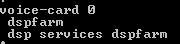
Allocating DSPs to a DSP Farm on Router
1

Then i Start to Configure the DSP-farm profiles for Each (MTP, Transcoder and Conference)
3

4

5
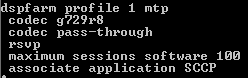
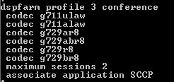
Note.Make Sure to Issue Command No Shut after Each Profile Configuration
After the profiles are set up i start by the SCCP Configuration
The routers use their Gigabit Ethernet 0/0 interface as the SCCP source interface, and the primary Cisco Unified Communication Manager should be 192.168.200.229 which my Publisher and for Better Practice it should be the Subscriber but i Only have one in  the Lap

2
Last thing in IOS I Configure the SCCP Group
associated the CUCM with priority
associated Each Media Profile and Register with a name that i will use later in the CUCM Registration

6

Now the CUCM Part first start with MTP
go to Media Resource – Media Termination point – Add New
Select Cisco IOS Enhanced Software Media termination point
put the Name in the IOS which (MAINMTP)
Select the Device pool
Save – Reset
7
Now the Transcoder
go to Media Resource – Transcoder – Add New
Choose Cisco IOS Enhanced Media Termination point
Choose Device Name Configured in IOS Whcih (MAINXCODER)
Select the Device Pool
Save – Reset8
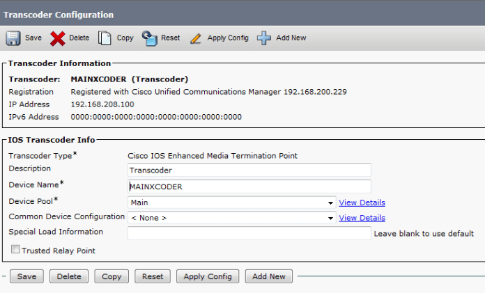
and Last the Conference
go to Media Resource – Conference Bridge – Add New
Choose Cisco IOS Enhanced Conference Bridge
Choose Device Name Configured in IOS Whcih (MAINCFB)
Select the Device Pool, Location and Device Security Mode as Non Secure
Save – Reset9

Last But Not Least to Configure MOH
Add the Audio File
Media Resources – MOH Audio File Management – Upload File From Desktop
1
2
3
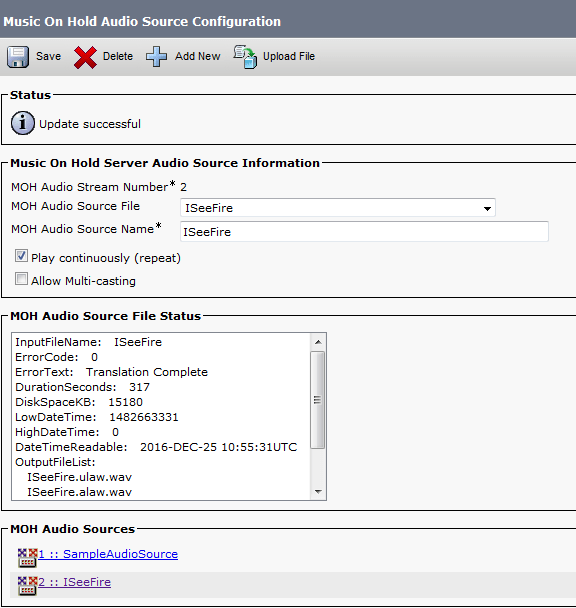
Then Create an MOH Source
Go to Media Resources – Music On Hold Audio Sources – Add New
Choose Number and Select the Audio Source that you Just Upload
4
Last Thing is to Configure the MOH Server
Go to Media Resources – Music On Hold Server Audio Sources
Select the Device Pool, Location
Note.in Case of Multi Casting then you need to Check the Box for Enable Multi-cast Audio Sources on this MOH Server5
Now Assign the MOH to the Phones
7Finally we Done with the Resources, it’s Time to add them all Under one group
go to Media Resource – Media Resource Group – Add New
Name it in my Case i Name it (MainOffice)
Choose the Resource you Just Configured (MAINMTP, MAINXCODER, MAINCFB and MOH_2 (MOH))
Add them
Save
6
Note.Also be Aware in case of Multi casting you need to Check the Box Use Multi-cast for MOH Audio (If at least one multi-cast MOH resource is available)
Now Create an Media Resource List and add the Group to it
go to Media Resource – Media Resource Group List – Add New
Name it in my Case i Name it (MainOffice)
Choose the Media Resource Group I Just Configured
11
Finally Assign the Media Resource Group List to the Device pool
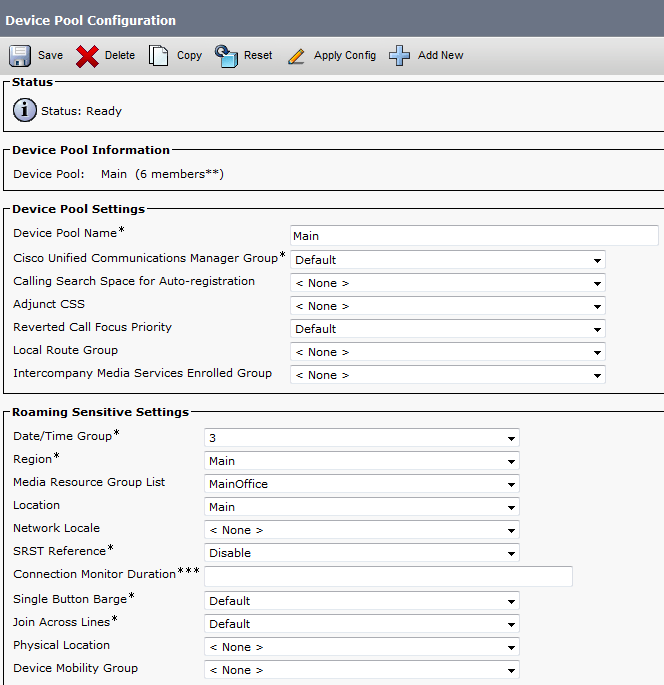
 12
And Done
now you Allocated the Media Resource List i Configure for Each Member of this Device Pool

For Conference check this Link
For Music on Hold Video check this link
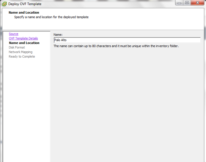
Standard