BGP

BGP Peer Groups

Happy New year (2026) and welcome to my first blog in ths year

last year which is two weeks ago I show you how to configure basic configuraton for BGP and publish the internal network but now  i have more BGP Peers and let say i have a 1000, that would be annoying to add all those command so the soluton is (Peer Group).

A BGP Peer Group is a configuration feature that bundles multiple BGP neighbors sharing identical outbound routing policies into a single logical entity, simplifying management and improving efficiency by processing updates once for the group instead of individually for each peer, saving CPU/memory. Another way to explain it, a peer-group is a set of BGP neighbors that shares the same Configuration/policy.

Configuration:

On my Simple scenario i have two neighbour so let’s do it
1
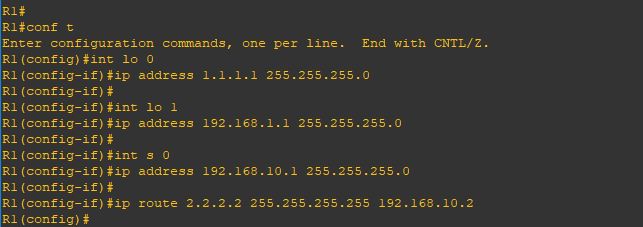
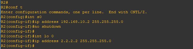
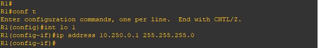
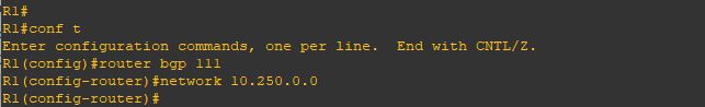
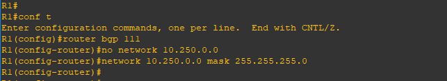
i have my interfaces configure for R12
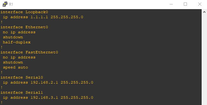
i add a static route for the loopback interfaces of Router2 and Router32a
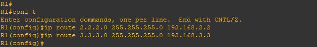
I will repeat the same for other routers3
and static route only to Router1 Loopback
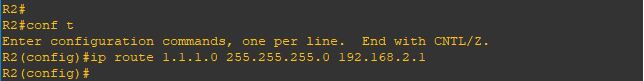
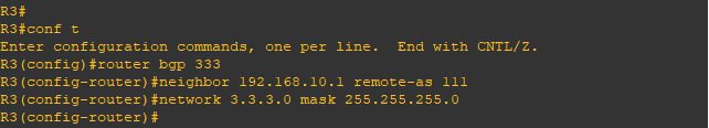
3a
and last one is R3
4
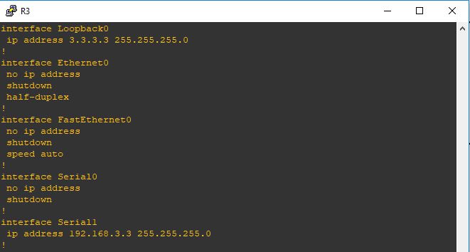
and static route to Router1 loopback4a
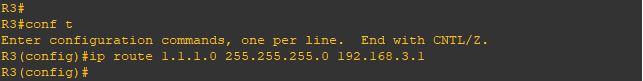
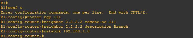
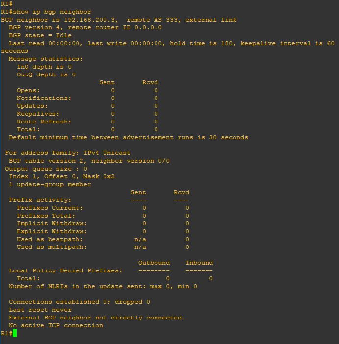
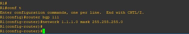
Now the first thing in R1 i will configure the Neihbor command to R2 and R3 loopback5
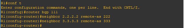
Then i will add both neighbor to a peer-Group (Routers)6
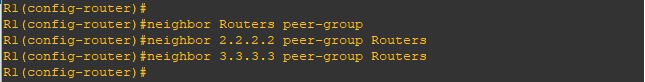
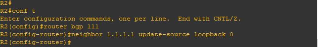
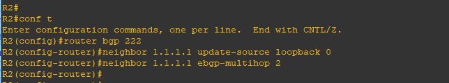
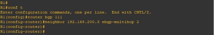
Now the loopback interface and ebgp multihop will be added under the Peer-group (Routers)
and that will affect the configuration of both my peers7
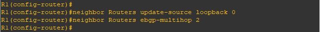
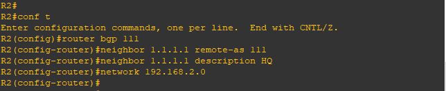
on the Peer R2 is the normal configuration and nothing extra needed
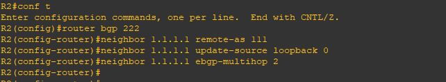
8
Same in R3
10
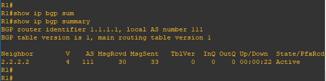
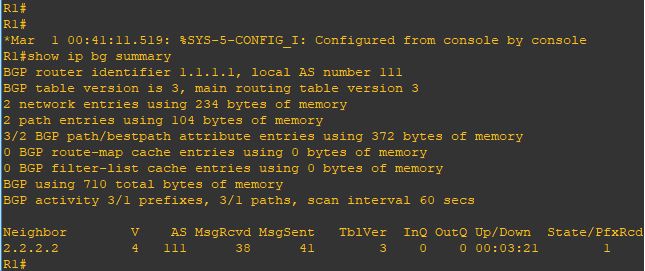
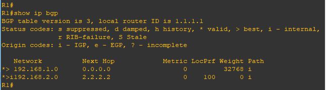
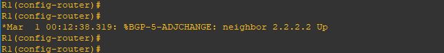
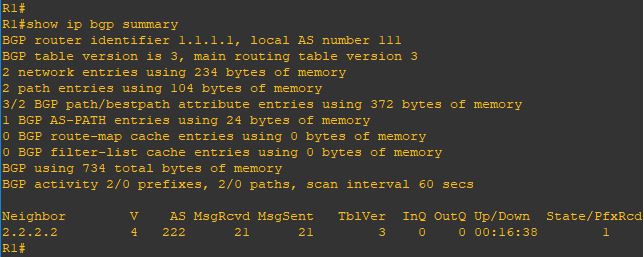
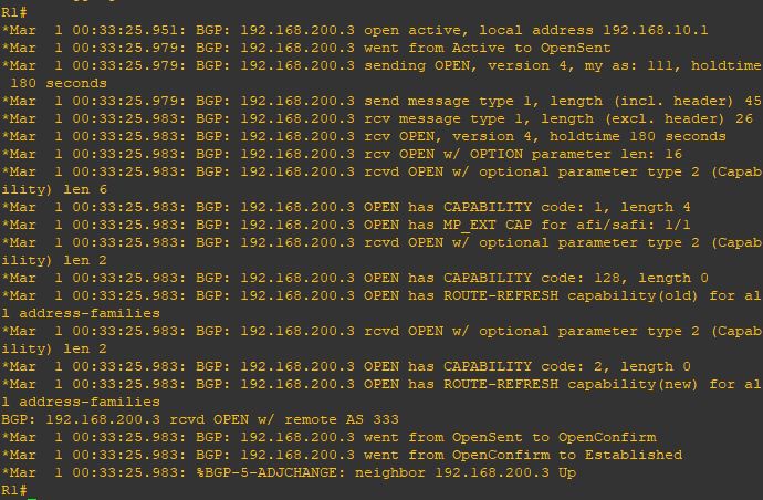
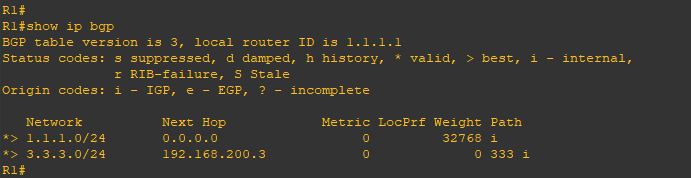
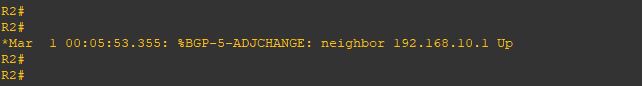
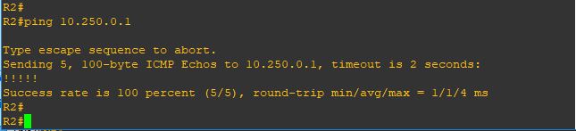
and as you can see it worked so fine and my BGP is up
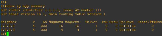
11

Note:
  • This is just a simple scenario but you can utilize the Peer-Group Instead of configuring each neighbor with the same remote-AS, route-maps, or filters, you apply them to the group, and members automatically inherit these settings, though inbound policies can often be customized per neighbor
Standard
BGP

BGP Using Loopback

I show you in the previous blog how to establish neighbourship between BGP using the Physicl Interface of the Router but today we will use a different appproach with a technology called {LOOPBACK}.
Using loopback interfaces for BGP neighbors provides stability by ensuring the session stays up even if physical links fail, as loopbacks are always on, but requires an Interior Gateway Protocol (IGP) like OSPF to advertise them and the update-source command to source BGP packets from the loopback.

1
from the picture above you can see my scenario is an iBGP neighbourship so let’s start
First i configure the IP Addresses on both Routers with making sure an extra step which is Reachability.
The loopback IP address must be reachable via an IGP (OSPF, EIGRP, IS-IS) or static routes.
2
Repeat the same steps on Router 23
Now i will configure basic BGP neighbourship command and sharing my network using the network command
4
i will repeat the same steps on Router 25
Now we will check the status of our neighborship and ….
oops [ACTIVE]
no one want to see this
BGP Neighborship in the ACTIVE state means the router is actively trying to establish a TCP connection with its peer by initiating the connection on port 179, but the handshake hasn’t completed.
6
and let me see the detail
you can see in the last line [No active TCP Connection]7
we are missing the most important command [update-source loopback 0]
telling the BGP Router to use the loopback interface as the source of conenction
8
Repeat the same step on Router29
YESSS and the neighbor cames up10
And also im receiving a prefix from my neighbor11
Issue the command [show ip bgp]
i can see the network i received12

That was the iBGP case
but what if we had an eBGP situation and we are using the loopback

1
so its different when both router in different AS and the line before the last shows a new error
[External BGP neighbor not directly connected]
6
so we need to add a different command
[ebgp-multihop] which increases this TTL value as the default is 1
7
Repeat the same on Router 28
and YESSS the nighborship cames up9
and now im receiving the prefix again
10
and i can ping my neighbor internal network11

Note:

  • By default, eBGP uses a TTL of 1, which means routers must be directly connected. If a BGP router is more than one hop away, the TTL decreases from 1 to 0, and the packet is discarded. The ebgp-multihop command increases this TTL value, enabling BGP neighbors to be multiple hops apart.
Standard
BGP

eBGP Multihop

Welcome Back
in the previous blog i show you how to establish BGP Neighbourship using direct connection BUT what if the neighbor were not directly connected the solution is (Multihop). By default eBGP uses a TTL of 1 (multihop) increases this TTL value which enable BGP neighbors to be multiple hops apart.

this is my GNS3 Scenario:1
Now this is the configuration on R2 but also in each router i need an [IP Route] to the other Router2
Then i will configure the basic BGP neighbourship which i explain in the previous blog
3
Repeat the steps for R3
4
Now when issue the command (show ip bgp summary) you can see the neighbor stuck on status (idle)5
to see more detail i will issue the command (show ip bgp neighbor) you see in the last line in the picture it mention (External BGP neighbor not directly connected)
7
so now let me add the magic touch (ebgb-multihop 2)
2 is the number of the hop8
also in the other neighbor 9
I add the debug command so i can see the result10
and as you can see the neighbor is up11
and now as you can see the status change and i receive 1 prefix from my neighbor12
and everything is perfect 13

Note:

  • By default, eBGP uses a TTL of 1, which means routers must be directly connected only and If a BGP router is more than one hop away, the TTL decreases from 1 to 0, and WAK WAK WAK the packet is discarded.
  • in case the connection is direct between eBGP that is TTL of 1 so it will check if neighbor in the same subnet but im using loopback then configure (neighbor x.x.x.x disable-connected-check) on both router
Standard
BGP

Basic BGP Configuration

The Biggest Routing Protocol in The World
in 2011 i created me and my earlier Manager Wahiduddin [TIKO] a group called [BGP For Life]

and Implemented an over 10 BGP Site and reach to 30 Site in 2 year and i fell in love till VOIP Came and got engaged in it for a while, so i decide to create my BGP blogs.

i will walk you through my BGP Series how to configure BGP in every way i know ;D

We have 65535 number we choose from our AS just like private and public IP addresses:

  • 0 : reserved.
  • 1-64,495 : Public AS numbers.
  • 64,496 – 64,511 : reserved to use in documentation.
  • 64,512 – 65,534 : Private AS numbers use for customer and my LABs.
  • 65,535 : reserved.

So BGP Resume:

  • It use TCP-Based Port 179
  • Triggered Update 5 Second Internally and 30 Second Externally
  • Complicated “Metric” for finding the best route
  • Neighbors Manually Configured
  • BGP Packets (Open, Update, Keepalive & Notification)
  • BGP Status (Idle, Active, Open Sent, Open Confirm & Established)

I will use GNS3 for my Labs so let start by configure basic connectivity between two router

1
i will start by configuring the interface for R1 and loopback 2
Then proceed with R2
3
Now the BGP Neighbor Configuration on R1 by first mention the AS number of R1 (remote-as)
then the first command for our neighbor is by typing their IP Address of Router and their AS number
6
Repeat the same step on R2
7
Finally the neighbor came up8
Same in Router 2
9
Now i will Issue the command (show ip bgp summary) which is a quick overview of your Border Gateway Protocol neighbor status, showing neighbor IPs, ASNs, BGP state (Idle, Connect, Established), uptime, and the number of prefixes learned/advertised, helping quickly spot peering issues or route exchange problems
10
repeat the same command on R211
Now i will tells a router to advertise specific IP prefixes to its BGP neighbors by issuing the command
(network x.x.x.x mask x.x.x.x)
12
Repeat the same on R2
13
and now you can see the network that been advertise to you by issuing the command
(show ip bgp) and if you look at the local network on my router [1.1.1.0/24] have a weight of (32768)
which is local to me but the other network [2.2.2.0/24] have a path of an AS 222
14
Same on R2
15
test connectivity using [ping] and it goes very well16
if you look above we advertise the network using (network x.x.x.x mask x.x.x.x) because unlike IGP protocols, it only injects routes that already exist as exact matches (network address and subnet mask) in the router’s local routing table. let me show you

i will configure the new loopback 1 with a /24 mask
20
and advertise it without mentioning the Mask 21
and as you can see it doesn’t show up because the BGP will advertise the default subnet mask for the network (10.0.0.0) which is (/8) and that subnet not available under my network 22
so let’s correct it
23
and Wallaaaaaaa
24
and yup i can ping it
25

Note:

  • IBGP administrative distance of 200 while EBGP is 20
  • When your router learns about a prefix through EBGP and an IGP (RIP, OSPF or EIGRP) then it will always prefer the external BGP route. EBGP uses an administrative distance of 20 so it’s preferred over OSPF (110), RIP (120), or EIGRP (90).

Standard
Conference

Conference Now

CUCM 11 New Feature
replacing the present Meet-Me feature
well let me tell you, finally i got the approval from Management to upgrade our CUCM and since then i have to read alot to see which new feature i have and one of the newest is Conference Now
i show you earlier how to configure Meet-Me Conference so today i will show how to configure the Replacement for that feature, and You can now set a PIN to the Meet-Me feature, making it more secure Similar to Webex
So i Download CUCM 11 ISO File and i will configure this in the 60 Days Demo License
and as you can see the home page look different
a
Login with my Username and passwordb
and here show the System is operation on demo license
don’t worry about it
the feature will work on it
1
First go to Call Routing Tab – Conference Now2
Enter the Conference Now Number3
Then go to Media Resource – Interactive Voice Responses4
Make Sure the IVR is registered to the CUCM5
i will Change the Device Pool and Location to my Site (Jamjoom)6
Now go to Media Resource – Announcement 7
Here i can check the All the Default Announcement and as you see the First couple of Announcement is belong to Conference Now Feature and i could change it too for a custom recording 8
Now go to User Management – User/Phone Add – Feature Group Template9
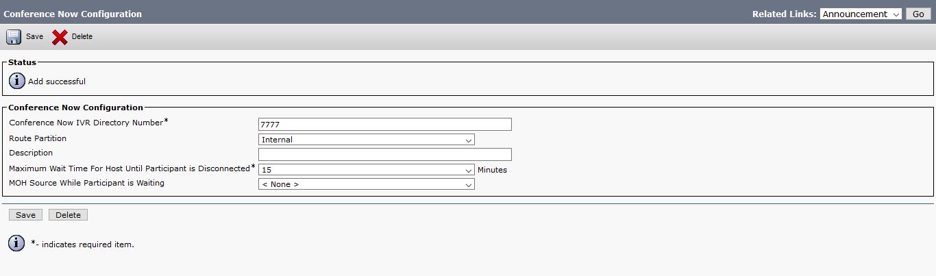
in the Default Group Template select the Box – Enable End User to host Conference Now10
now go to Configure End User under User Management Tab11
Configure the Self-Service User ID for the End User12
Select the Primary Extension13
The Last Most Important Step is to Enable the Box under Conference Now and make sure the Meeting Number is the same as the Self-Service user ID
and to make sure your Conference is Secure configure the Attendees Access Code14
like that your configuration is Complete
to check the number allowed for Conference is the same like Meet-me feature
go to Service parameter – Choose the server and Call Manager service15
and As you see you can Adjust everything here16

Now lets Check the Video for testing the Conference Now Feature


Standard
Conference

Video Conference

This is the Cisco IP Phone Biggest Feature of all

Video Conference is one of the Major thing in Business were Some Employee reside in another City and you can save time and Money with Video Conference and for Some Business an MCU is not an Option.

The Best thing for it to work You don’t need TelePresence or Meeting Server, All what you need is a PVDM3 Modules weather it  PVDM 3-128 or PVDM 3-265 in your Router and Configure the Conference in the IOS Similar like you do the Normal Conference i already Explain it in an Earlier Blog

I will be configuring Video Conferencing for Cisco 8941 IP Phone and 2 of 9971 IP Phones.

So Let Start Configure the IOS

first i Set the DSP reservation for voice related services Integer is a percentage which is 60 in this Example, That Leave me with 40% to video resources

1

Then Configure the Video Conference Profile

Its Important to  Define the conference-participants parameters and Maximum Sessions so I Define how Many Parties Per Conference and I define Also the maximum sessions

3

Now the SCCP Configuration Part

i Define my Call Manager

2

and here i Associate the Video Conference Profile to the SCCP Group

4

Now the CUCM Part

Go to the Media Resource – Conference Bridge – Add New

5

Then  Go to Media Resource – Media Resource Group – Add new and Select the Video Conference Resource that you Just Configure

6

Then  Go to Media Resource – Media Resource Group List – Add New and Select the Media Resource group

11

Finally Assign the Media Resources Group List to the Device Pool

12

Now make a Call to from Phone A (7156) to Phone B (4119) then i Add by Using the Conference Button https://i0.wp.com/www.cisco.com/c/dam/en/us/td/i/200001-300000/250001-260000/255001-256000/255303.eps/_jcr_content/renditions/255303.jpg 
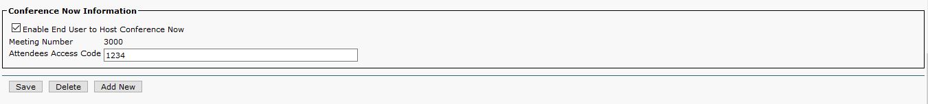
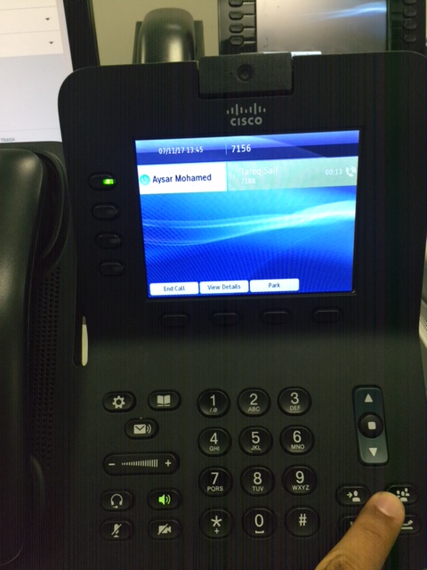
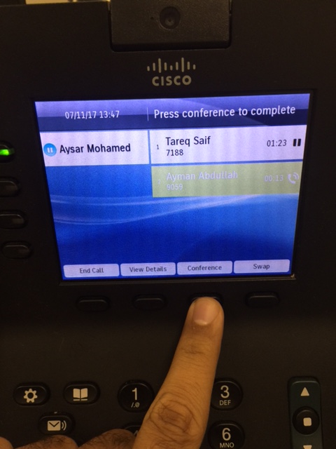
and Add Phone C (2131) and Press the Softkey Conference and Just Like that you have a Video Conference
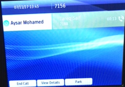
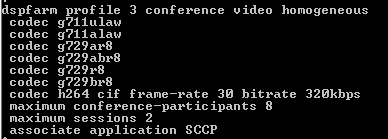
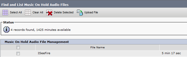
you can watch the Video in this Link
or you can see it in the video below

Note. Cisco release a Feature Deprecation Announcement for Video Conferencing and Transcoding Using PVDM3 on ISR G2 Product Bulletin Feature Deprecation Announcement for Video Conferencing and Transcoding Using PVDM3 on ISR G2 Product Bulletin were saying “This feature will be disabled with Cisco IOS Software Release 15.5(3)M” so in case you want to use it Youre going to have to roll back to an older release.

Standard
Conference

Ad Hoc Conferencing

Conference Cant get Any Easier  ;D

I already explain in earlier blog the other Conference Feature Meet-me and in my Believe Ad-Hoc is the Advanced feature of Conferencing

in Ad-Hoc the Initiator of the Conference which is the Controller would have the  ability to view the List of the Other Parties, to Remove Some of the Parties. Also you can provide this  Feature to the other parties to have same capabilities of the controller

First just like Meet-Me you need to have conference resources available on you router before you can use any conference features i already explain how to configure a Conference Bridge in earlier Blog Media Resource Group

no other configuration needed

so to start conference first i will go to My Cisco 8941 phone and Make call for the First Parties which in my example is extension 7188

Untitled

After the first parties answer then I Press the Conference Button

Conference Button.png

on the 8941 and Call Second Parties extension number 9059

IMG_6697

IMG_6702

After 9059 answer then press Conference Softkeys to Add him to  the Conference

IMG_6705

And it’s now everyone join the  Conference and you can add as many user that your Conference Resource can support

You can view the List of Parties by press View Detail Softkey

IMG_6707

Detail

Also you can select a user and remove him from the Conference

IMG_6709.JPG

its a really great feature and user will not have to go through System Administrator to ask for a Number to call like Meet-me Conference were you need it

to adjust your conference to protect your self from toll fraud you can configure the call to be terminated once the controller drop the call

Go to System – Service Parameter – Select the Server and Choose the service (Cisco CallManager ) then go to Clusterwide Parameters (Feature – Conference)

Drop Ad Hoc Conference : When Conference Controller Leaves

10

Also if i want to other Parties non-Controller to View List of Conference parties and Remove other Parties i will go to System – Service Parameter – Select the Server and Choose the service (Cisco CallManager ) then go to Clusterwide Parameters (Feature – Conference)

Advanced Ad Hoc Conference Enabled : True

20

Also you can increase number of Parties to join conference, the default value for this Clusterwide Service Parameter is 4.

;D

Standard
Conference

Meet-Me Conference

So i got request from one of the Top Manager in Jaguar Land Rover to have a way to make a conference in his phone for Daily basis

will conferencing one of the most important things in any Enterprise this days,  it save traveling and timing and get to the point ASAP.
Cisco made the implementation of conference easier with Meet-Me Conference so let me guide what you will do when a user Ask you to get to a meeting

So lets go to the Configuration part

First requirement is to have conference resources available on you router before you can use any conference features i already explain how to configure a Conference Bridge in earlier Blog Media Resource group

so after that go a head to Call Routing – Meet-Me Number/Pattern – Add New
Choose a unique Number Ex.: 9876 and partition

1
in case you have a custom Softkey template Then Add the Meet-Me Softkey to the Off-Hook state
(another option is to configure the Meet-me as a button)
Go to Device – Device Settings – Softkey Template – Add new
i named it (Meet-Me)
2
Then Go to on the right corner to Configure Softkey Layout
then select the state Off-Hook from drop down
and Move the Meet-me to the Selected Softkeys and Save
3
Now go to the phone were  you need to initiate the Meeting and Assign the New Softkey template to it which we configure
4So to Procedure
go to the Phone to initiate the Meeting
while the phone in  off hook state press softkey meet-me and press the Number which we configure earlier 9876 which is Meet-me Directory number
IMG_6689
After that put the Meet Me unique number 9876IMG_6690
and Like that you enter the Conference RoomIMG_6691
now go the other Parties and Let them just call 9876 simply like they dial any directory number
2.JPG
and Walla they Enter to the Conference Room3.JPG

and that’s a wrap

**the meet me can hold as many Parties as your resource can support**

Standard
IOS

SSH (Secure Shell)

as a network administrator our job is to protect our network
well there is too many ways and telnet is  not one of them
using hacking software can show the Password in a clear text so now you fired

Secure Shell (SSH) is a cryptography network protocol provides a secure channel over an unsecured network
i will guide you in the way to configure it in Switch

First Configure the Hostname
1
Then Configure the Domain Name2.png
Then Generate Key and Choose your Encryption 3
Last thing Enable SSH Version
4
Finally under VTY Configure the Transport Input to Allow SSH only5
Now Configure the User 6
Now there is many tools you can use for SSH
I Choose Putty
My Switch IP : 192.168.188.5
Connection Type: SSH
7
Accept the Security Alert
8
Login with my User that i created earlier
username:ccieroot
password:ccieroot9
That it  ;D

Standard
CUCM, Media Resource Group, Uncategorized

Media Resource Groups

The Most Important Element in CUCM World is the Media Resource. it’s used in order to allow an administrator to allocate media resources to particular devices.
There are five types of media resources available in Cisco:
Annunciator, Conference Bridges, Media Termination Point, Transcoder and Music On Hold
Annunciator is uses Cisco media streaming application service to play prerecorded announcements

Conference Bridges Without Saying it explain it self and can be either software or hardware applications

Media Termination Point or MTP can be used to transcode G.711 a-law audio packets to G.711 mu-law packets and vice versa. CUCM Software MTP can only work for G711 codec, however IOS MTP can have multiple codes

Transcoder when two Phones using different codecs would not be able to communicate so here were the Transcoder Job Come
Such Case Like conferencing, CUE use only G.711 so if another Coded used you need Transcoder, UCCX Support G.711 or G.729 so in case you need Both you need a Transcoder. Forward and transfer Call in case of Different Codec Also you need a Transcoder.

Music on Hold is the Boring Music that everyone hear when someone put us in hold ;D

So here i will guide you on how to configure my 4 Most Charming Feature (MTP, Transcoder, Conference and MOH)

First We start by Configure the IOS Side
Allocating DSPs to a DSP Farm on Router
1

Then i Start to Configure the DSP-farm profiles for Each (MTP, Transcoder and Conference)
3

4

5
Note.Make Sure to Issue Command No Shut after Each Profile Configuration
After the profiles are set up i start by the SCCP Configuration
The routers use their Gigabit Ethernet 0/0 interface as the SCCP source interface, and the primary Cisco Unified Communication Manager should be 192.168.200.229 which my Publisher and for Better Practice it should be the Subscriber but i Only have one in  the Lap

2
Last thing in IOS I Configure the SCCP Group
associated the CUCM with priority
associated Each Media Profile and Register with a name that i will use later in the CUCM Registration

6

Now the CUCM Part first start with MTP
go to Media Resource – Media Termination point – Add New
Select Cisco IOS Enhanced Software Media termination point
put the Name in the IOS which (MAINMTP)
Select the Device pool
Save – Reset
7
Now the Transcoder
go to Media Resource – Transcoder – Add New
Choose Cisco IOS Enhanced Media Termination point
Choose Device Name Configured in IOS Whcih (MAINXCODER)
Select the Device Pool
Save – Reset8
and Last the Conference
go to Media Resource – Conference Bridge – Add New
Choose Cisco IOS Enhanced Conference Bridge
Choose Device Name Configured in IOS Whcih (MAINCFB)
Select the Device Pool, Location and Device Security Mode as Non Secure
Save – Reset9

Last But Not Least to Configure MOH
Add the Audio File
Media Resources – MOH Audio File Management – Upload File From Desktop
1
2
3Then Create an MOH Source
Go to Media Resources – Music On Hold Audio Sources – Add New
Choose Number and Select the Audio Source that you Just Upload
4
Last Thing is to Configure the MOH Server
Go to Media Resources – Music On Hold Server Audio Sources
Select the Device Pool, Location
Note.in Case of Multi Casting then you need to Check the Box for Enable Multi-cast Audio Sources on this MOH Server5
Now Assign the MOH to the Phones
7
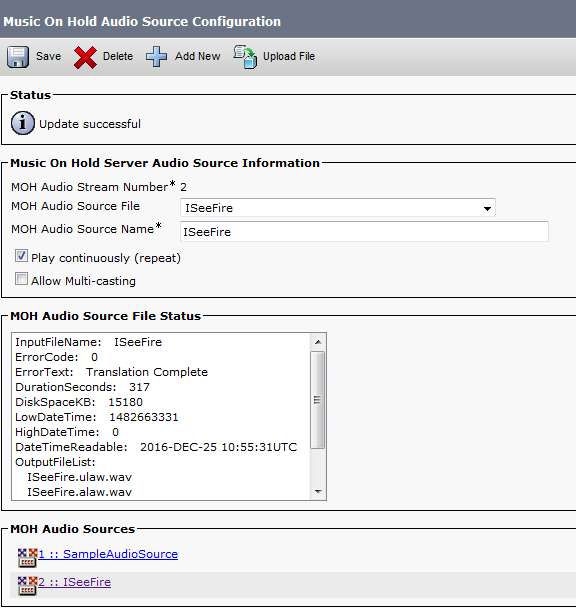
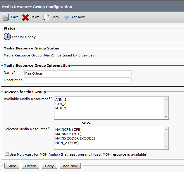
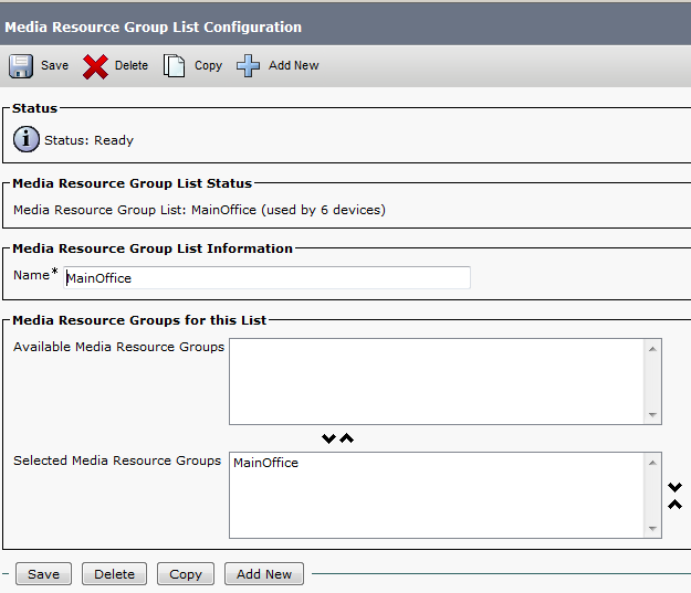
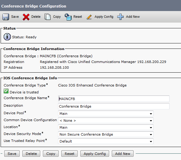
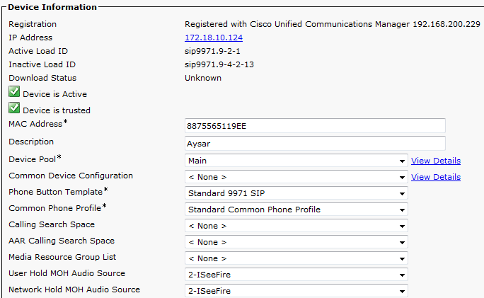
Finally we Done with the Resources, it’s Time to add them all Under one group
go to Media Resource – Media Resource Group – Add New
Name it in my Case i Name it (MainOffice)
Choose the Resource you Just Configured (MAINMTP, MAINXCODER, MAINCFB and MOH_2 (MOH))
Add them
Save
6
Note.Also be Aware in case of Multi casting you need to Check the Box Use Multi-cast for MOH Audio (If at least one multi-cast MOH resource is available)
Now Create an Media Resource List and add the Group to it
go to Media Resource – Media Resource Group List – Add New
Name it in my Case i Name it (MainOffice)
Choose the Media Resource Group I Just Configured
11
Finally Assign the Media Resource Group List to the Device pool 12
And Done
now you Allocated the Media Resource List i Configure for Each Member of this Device Pool

For Conference check this Link
For Music on Hold Video check this link

Standard