First i have to apologize cause this going to be a long Trip and it my fault i didn’t research it will but to deny an SSL traffic which used by facebook first you have to read what inside it, in another word (Decrypt it)
So i’m here rewrite the article again and just add the Decryption of the traffic before it forward to the intended site
First we need to create a Certificate on Firewall
Choose a name, Common name and Check the Certificate Authority
and the Certificate Attributes then Click Generate

Now Select the Cert to Edit and Check the Box
Forward trust Certificate
Forward Untrust Certificate
trusted Root CA

Then Export the Certificate as (PEM)

Choose Place to Save it
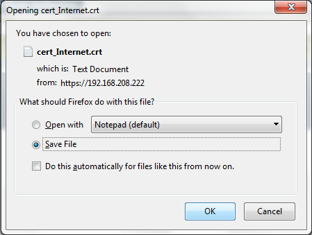
and as you see it download it in my Download Folder
Second i will go to my laptop to import in
Go to Tools – Internet Option – Content – Certificates

Go to trusted Root Certification Authorities Tab – import
Press Next

Browse to my Certificate

Choose to place it in the Trusted Root Certification Authorities
Press Finish

it will give you a security warning just press yes
and import is successful
you can check it under the Trusted Root Certification Authorities Tab

Now get back to Palo Alto and Configure the Decryption Policies
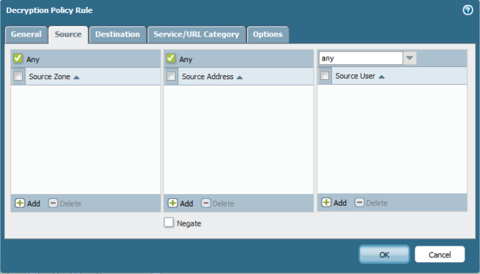
Go to Policies – Decryption – Add
since this is a lab i will Choose Any as the Source
Also Choose Any as the Destination 
i can Adjust under URL Category but since this is a lab i will configure it as Any
Under option Tab i select the Action as Decrypt and Type SSL Forward Proxy
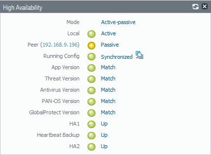
Now i Check Gmail and here its Secure from my PA-CCIEROOT which is my Palo alto Common Name
Also my facebook is Secured 
;D
Now that was the Part that everyone kept ask why Aysar it ain’t working
your article is wrong
will i hope it work now
So as i said earlier unless you work in Marketing then you don’t need any Social Website
so Aysar Mohamed (ME) is an IT guy and i want my self to do IT Work and stop playing around the Facebook
(i am sure my manager agree in this point) so let’s do it
First I need to tell you when using Application you need to be careful what you choose
you can select application using Category, Subcategory, technology, Risk and Characteristics
sometimes you see if you choose based on Risk level 5 which is the hardest you could break google drive
and if you use the application using Characteristic and choose Vulnerability you could break SIP so Review everything.
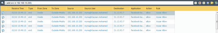
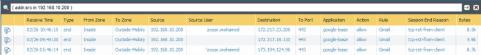
Now go to Monitor – Logs – traffic and as you can see it full by Facebook logs by Aysar and it depend on one Application (facebook-base)
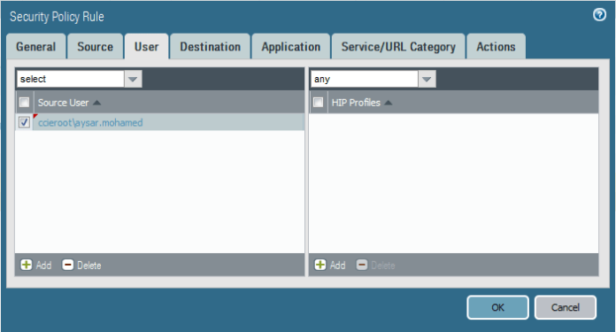
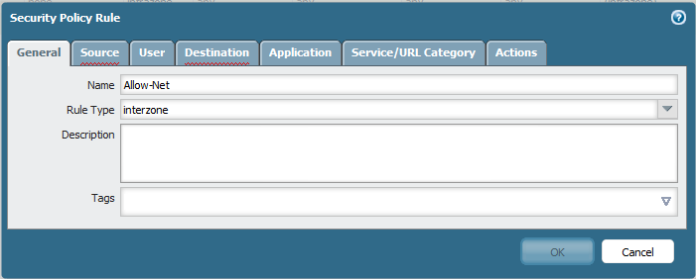
So let go to Policies – Security – add new (Stop facebook)
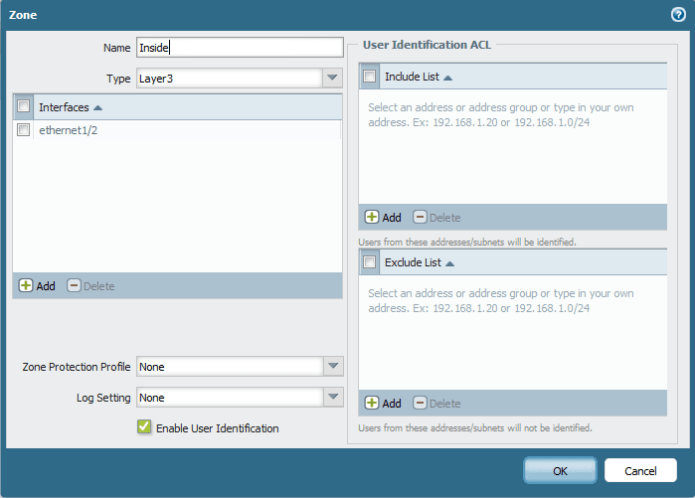
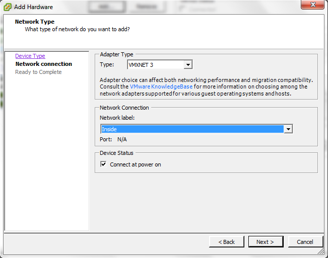
Select the Source Zone (Inside) and Source Address (My Laptop IP Address)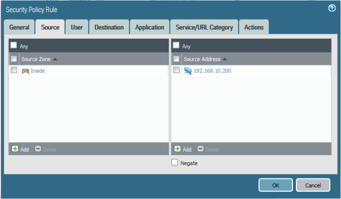
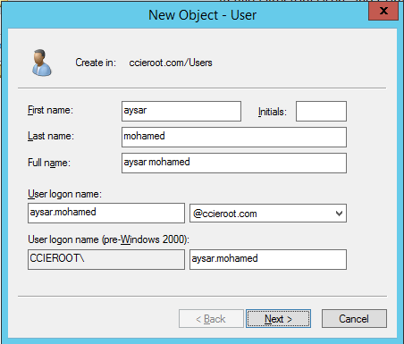
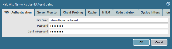
Select my user (Aysar.Mohamed)
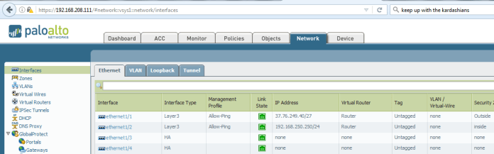
Select the Destination my outside interface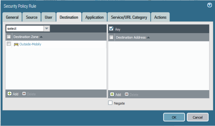
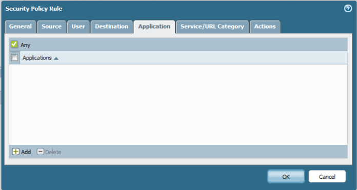
then here choose the application (facebook-base) which appear in my logs
sometimes you need to add
(Web Browsing), (SSL) & (DNS)

Now Choose action to deny

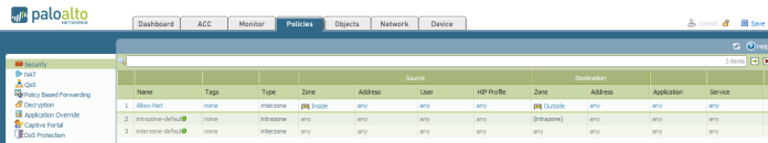
Make sure to move this rule to the top

As you can see now i cant open my facebook at all and it give me this error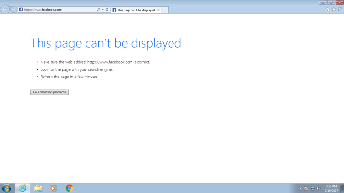
and if you go back to the logs you will see the action (reset-both) Now what if i want Aysar to view his Facebook but don’t want him to Chat with Anyone
Easy go back to my (Stop facebook) Policy change the APP-ID to (facebook-chat) and save
some application can’t just stop by choosing the APP-ID you need to select also what it depend on
so highlight the rule and go to the application tab and choose facebook-chat and right click and choose (Value) to see what its Depends on.
so for facebook-chat it depends on
facebook-base
mqtt
Now If i select facebook-base it will also block facebook page Also
so here the trick

Add only mqtt

Then in my Second Rule (Aysar Allow) i will add to Alow the facebook-base
under Application i will only add the facebook-base
Now i can go to my facebook but as you can see my Chat is Dark (Unable to connect) 
and as you can see in the Logs it block the facebook-chat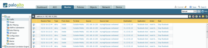
;D
(if you need to check list of App-id you can use, go to Object tab – application)
Happy Friday Everyone


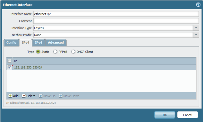
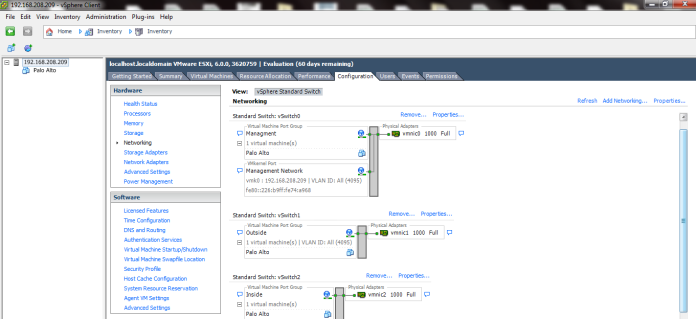
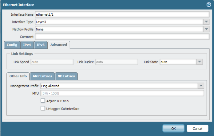
 Then Configure Ethernet 1/2 for DMZ gateway


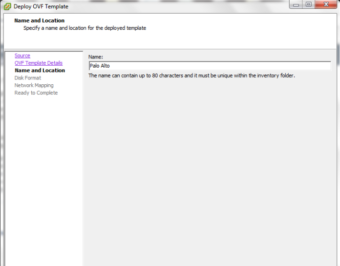


 Now we Finished with The Installation of the OVA
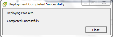


 Then Create an MOH Source
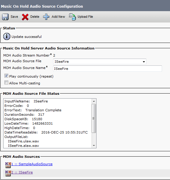

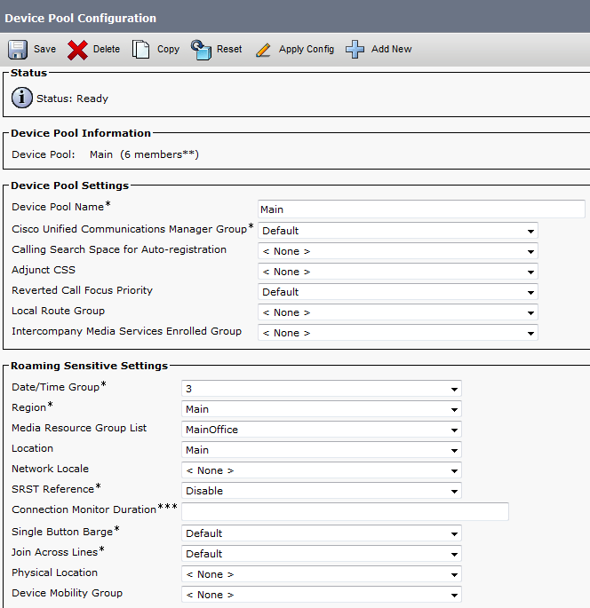
 Finally we Done with the Resources, it’s Time to add them all Under one group