Troubleshooting, Upgrade Software

Troubleshoot Access Point Not Joining a Wireless LAN Controller

have you face a problem installing a new Access Point Model
A week ago i Receive a new Access Point Model 1702I and as always insert the join command to the controller and it reject to join the Team and after hour of debugging i found out that my WLC software 7.4.110.0 is not supported for this Model

900

you can check this link from Cisco to check which software could support your Access Point http://www.cisco.com/c/en/us/td/docs/wireless/controller/release/notes/crn80mr2.html

So i open a ticket with Cisco TAC and let me tell you i always enjoy working with such an Expert like Cisco TAC

I show in earlier blog how to install WLC

First i need to download the Image from Cisco Web Site https://software.cisco.com/download/navigator.html?i=!mmd

and Navigate to your WLC Model, we have 5508 but you should have a valid service contract 1i Choose the WLC Software
2

and i Choose the Firmware that Cisco Suggested Depend on Software quality, Stability and Longevity. i think this a new Cisco thing since i didn’t see this option last year were they suggest which one is better3

4
I Download it to my Laptop and Save it to a folder and used a TFTPD32 Open SOurce software which can be downloaded from http://tftpd32.jounin.net/
5
then in the WLC i go to Command Tab and choose Download
File Type: Code
Transfer Mode: TFTP
Server Detail
IP Address: My TFTP IP Address in my case (192.168.208.69)
File Path: /
File Name: My Software Name in my Case (AIR-CT5500-K9-8-0-121-0.aes)
Then Press Download
6
you can see the under the TFTP transfer procces start in the TFTD32 Software and also in the Command Download Page in WLC
78
it took almost over 40 minute then go to Commands Tab then CHoose Config Boot You will see that the Primary Image Change from 7.4.110.0 to 8.0.121.0
9
Now i need to Reboot the WLC to make the New Image act as the Active one
Save and Reboot
10
After the Reboot go to the Monitor Tab then look in the Controller Sumary and the Software Version Change also to 8.0.121.0
11
you can also go to Command Tab then Config Boot you will see that the New Image become Active
12
After that the wireless Start to download the new firmware and reboot13
Under Wireless Tab you can see the Operational Status for the Acess point is “Downloading”
14
and now All my Access Point is Okay15
and the new Primary SW Version is also 8.0.121.0
16
now to make sure my New Access point will Join the Team
first i configure the switch Port as normal
20
Then plug the Access Point and it start to take the new configurtion without any Debug Error
22
and i finally made another customer happy   ;D


Standard
Wireless, WLC

Installation of Virtual Wireless Controller (vWLC)

Iknow
I’m far away from Collaboration, but this what happen when you are an Infrastructure Engineering.
So The Virtual Wireless LAN Controller (vWLC) runs on Virtualization infrastructure. it’s ideal for small and mid−size deployments.

Today i will explain The Basic installation of vWLC on ESXi server
First need to download the OVA from Cisco web Site https://software.cisco.com/download/navigator.html?i=!mmd
Choose Virtual Wireless Controller
100
and Choose the Version that you need
101
i had old OVA in my PC so i didn’t download anything version 7.3.101
second we need to create two separate VSwitch
my ESXi server IP Address: 192.168.208.48
1
Select Virtual Machine
2
Choose the Network Card3
this is for Management Interface and for Vlan select ALL(4095) since this is connected to a switch trunk port
4

6
Do the Same for Service Port but choose None (0) for VLAN ID as the service port is typically an access port
6A
Now you can see both card
103
go to properties of the vSwitch1 were WLC is there and go to Security Tab and for Promiscuous Mode choose to Accept
104
Now start Deploy the OVA Template
7
Navigate to the Folder were i have my OVA
8
Next
9

10
Choose a Name for your Machine
11
Choose the Default Thick Provision Lazy Zeroed
111
Here Choose WLC were your NIC Card Configured for Management
13
Accept
14
Now the Machine is been created
15
for the first network Adapter just select the Service Port 15A
Now Power the Machine for the setup and monitor the Monitor till the vWLC has restarted Automatically16
then Start the Welcome Cisco Wizard
Choose you admin name
IP Address for Service & Management and DHCP
17
Also Choose the Virtual Gateway IP Address and Define your Mobility Group and NTP
if YES in Capital Letter you don’t need to write it cause its the default then you just need to Pres Enter18
Now it Ask you to Save
19
Now it will Reload
20
you can check your IP Configuration after login by using the Command
“Show Interface Summary”
20A
in the Web Page enter the IP Address that you Choose
HTTPS://192.168.200.25021
Press Login and it will ask you for Username and Password22
The First thing you will Notice that
0 Access Point Supported so we need to activate the Evaluation License23
Go to Management Tab and Choose Software Activation then License24
Open the base-ap-count and set the Priority to HIGH25
Accept the (EULA)
26
and Reboot so it will be Activated27
Now you can see the Different
200 Access point Supported28
Also you can check the Licenses base-ap-count status
28A
Now go to WLAN Tab and you can see the SSID Wireless that we Create in the Welcome Wizard but I will Create a New SSID from the option in the right corner
Create New Press the GO Button
29
Choose the Profile Name and SSID
30
Check Mark the Status box to enable
31
since this is a Lab we don’t need to put any Security so i choose None
32
Now lets Create an Interface
go to Controller Tab then Interfaces Create New
33
Choose Interface Name and Choose the VLAN ID
34
Now enter the full detail for the Vlan
VLAN Identifier
IP Addresses
and DHCP Address
35
Now I create Groups and assign the AP to a specific Group were it Broadcast specific wireless. we only have one and all SSID is under the Default Group but we will create a New one
Go Back to WLANs Tab then Advanced – AP Group – Create New
32A
Give it a Name and a Description
32B32C
Assign an SSID and Map it to an Interface and Save
32D
Now Start the Action with my Lab Access Point 1242AG
i know its old but old is gold so 36
I didn’t configure any DHCP Option for my WLC so i will use my magic Command to direct my AP to the controller
>lwapp ap controller ip address 192.168.200.250
and as you can see the Wireless start send request to the WLC and going to Download the firmware
37
Now under Wireless Tab i can see my Access Point i will change the AP Mode to FlexConnect since this is the mode supported by vWLC38
go to High Availability Tab and Enter the Controller name and IP Address
39
in Advanced Tab Choose the AP Group Name and change it to HQ group then Apply the wireless should reload and start to broadcast our SSID CCIEROOT40
AND HOLLA NOW I’M CONNECTED
41
i can go to Monitor tab in WLC and check the Client Summary
Click on Detail to See the Client42
and those my IPhone Mac Address and My Dell Laptop43
Done  ;D

Standard
UCCX

UCCX – Barge Features

Hi today I will show you a new feature of UCCX that I just implemented in Call Center of Hyundai.
In earlier blog I show you how to integrate the UCCX with CUCM

UCCX Integration with CUCM

today I will show you the Barge Features.
It allows the Supervisor to monitor Agents in their Team and Participate in the call and listen to the agent conversation with the customer.

From a Barge session, the agent see the call turn to a conference and the Supervisor can then intercept the call and drop the Agent from the call. and the Customer is now talking directly to the Supervisor.

First Enable in the phones for Built-in Bridge
1

Supervisor DN must have the Monitor CSS populated with a CSS that has access to the Agents DN Partition. it’s configured under the supervisor DN

2

now the supervisor should open the CAD Cisco Agent Desktop first then the CSD Cisco Supervisor Desk

3

4

Now Check the Agent That have a cal for example Agent7HYD have outgoing call to 7403
6

Select the Call and then go up you will see the button Barge-in Press it and suddenly the call turn to a conference
6

9

also you can intercept the call which result that the Agent7HYD will be Drop from the call and Supervisor Agent1HYD will be talking directly to the Customer 74037

The Same Configuration for CDA Cisco desktop Agent will go for the Cisco Finesse.


Standard
Cisco Jabber, Uncategorized

Installing and Configuring Cisco Jabber on IPhone

Long Time No See  ;D
i think by now everyone realize that cisco product Jabber Voice cant be downloaded in IPhone anymore which affect everyone as there EOL9796 – Amended
Cisco announces the end-of-sale and end-of-life dates for the Cisco Jabber Voice for iPhone. The last day to order the affected product(s) is January 31, 2015.

and i never cared after that till last week my manager Mr.Anas Aldeiri was in vacation and request to have his extension in his phone by any mean  and i start to keep looking and found out that there is another Cisco Jabber.
the New Cisco Jabber provide you by Chat, Phone Service, Conference and share photo

Last Post i show you how to Install & Configure IM and Presence 9.1 with CUCM 9.1 The Next step is to configure Jabber which can be done in a simple steps

First Just like you Adding a Normal Phone
Device – Phone – Add New
Cisco Dual Mode for iPhone
Then for IPhone Name Always start with TCTname and you should choose the Owner and the Primary Phone and the Digest User
1
2
3

Also enable video cause it’s disable by default
8

Second Add the Directory Number and Associate the Phone with the User

4
5
After that go to the User Option and Add the phone to the User
6

Now your Device is Ready go in your IPhone and Download from APP Store the Application Called : Cisco Jabber
2016-01-23 13.54.22

Please Excuse My Phone i dont Look at Email or SMS Alot
the APP Store Icon in Left Corner Down
2016-01-23 13.54.43.png

Now i Open the Application and Enter the Advanced Setting to Configure my IM Presence Option. you also can configure Phone Service Only or Webex
in Our Case My IM Presence IP Address is 192.168.200.10 and CUCM is 192.168.200.6

2016-01-23 12.19.53

Then Save and Back to Login Option
Put the Username and then Continue for Password Input

2016-01-23 12.20.08

2016-01-23 12.20.15

Finally I’m Done and You Can See i’m Available

2016-01-23 12.20.29.png

Then Let me Choose Contact to add my College Coco Test1 and Add him to a Company Group, I can also add him to my Favorite

2016-01-23 12.20.402016-01-23 12.20.452016-01-23 12.20.522016-01-23 12.21.032016-01-23 12.21.142016-01-23 12.24.16
I Click in the Right Arrow i can Call and Chat with my College COCO Test1 which he have Jabber in his PC

2016-01-23 12.25.14
2016-01-23 12.24.502016-01-23 12.25.202016-01-23 12.25.46
I have the Ability to Hold, Transfer and make Conference

2016-01-23 12.25.34

Inside the Chat i have the option to Send a Picture too

2016-01-23 12.27.48

2016-01-23 12.27.56

2016-01-23 12.28.042016-01-23 12.28.33

You can also have video call
File Jan 24, 5 13 50 PM

Also show me My Recent Call 2016-01-23 12.29.13

and the Status of my Jabber

2016-01-23 12.29.40

And Just Like That I made my Manager Happy

Standard
Collaboration

IM and Presence Integration with CUCM

Cisco Unified Instant Messaging (IM) and Presence is now better known as Cisco Unified Communications Manager IM and Presence (Cisco Unified CM IM and Presence). This is due to the integration of Cisco Unified Presence technology with Cisco Unified Communications Manager for Release 9.0 and later.

I will guide you through the installation
List of Software:
Cisco Call Manager 9.1.2
Cisco IM and Presence 9.1.1

let start by CUCM Side
first configure the SIP Trunk Security Profile
System – Security – SIP Trunk Security Profile – Copy the Non Secure SIP Trunk Profile –
Accept presence subscription
Accept out-of-dialog refer
Accept unsolicited notification
Accept replaces header
1

Then Configure SIP Profile
Device – Device Settings – SIP Profile – Copy the Standard SIP Profile
Allow Presentation Sharing using BFCP
3

4

Now Create Trunk to IM and Presence Server
Device – Trunk
2

5

6

7

Configure User Service
User Management – User Settings – UC Service – Add Cti, Directory & Presence

When it comes to Directory Integration for user lookup there are two options, EDI and UDS.

EDI – Enhanced Directory Integration requires no configuration by default. If you install Cisco Jabber for Windows on a workstation that is registered to an Active Directory domain, Cisco Jabber for Windows automatically discovers the directory service and connects to a Global Catalog in the domain.

UDS – User Data Service is an interface in Cisco Unified Communications Manager that makes contact information available to Cisco Jabber for Windows.

No server configuration is required for UDS. You create your directory source in Cisco Unified Communications Manager and then synchronize the contact data to Cisco Unified Communications Manager. After the synchronization occurs, your contact data resides in Cisco Unified Communications Manager. Cisco Jabber for Windows then automatically connects to UDS and performs all contact resolution.
8

9

10

Configure Service Profile
User Management – User Settings -Service Profile
11
User data service is a service that provide access to user informatin stord in the CUCM backend storage. Check the check box if select to use the UDS service provided in CUCM for the directory lookup instead of external directory.
12

13

Create the jabber-config.xml global configuration file.
you can use Jabber Config File Generator to do that or use mine
The following config file enables screen capture, file transfer and video. Potentially malicious files are blocked for file transfer such as exe, msi etc.
UDS is specified to use the Call manager as user search database which I will use in my document.
you can use Jabber Config File Generator to do that
Cisco File Generator:
Available by one of Cisco Web Page member Szelenka
https://supportforums.cisco.com/document/106926/jabber-config-file-generator

14

15

16

17

Upload the file to all TFTP servers, be sure to restart the tftp service on Pub/Subs.

Now Create the User and Assign the Service Profile to it
1

2

Now Create the Jabber Client
Device – Phone
Create a Client Service Framework Device. This is the softphone/desktop sharing used in Jabber for Windows. name it CSFuserid.
1

2

3

4

5

Goto the end user page. Add the CSF device and any desk phones to the end users device associations.
Add the Standard CTI Enable group.

7

1

Last Part in CUCM Side is Service Parameter Configuration
System – Service Parameter – Choose the Server – Cisco Call Manager
Default Inter-Presence Group Subscription : Allow Subscription
IM and Presence Publish Trunk : IM (the trunk i configure earlier)
1

2

Now Let’s Move to CUPS Side
First start the initial Setup
login to Administrator Applications
1
Put the CUCM name and IP Address and put the username and password for AXL Admin
2

3
Then put the security password for the CUCM Cluster dirung cucm installation
4

5

Now press the Home Button so you can go to the Home Page of the Server and like that the initial setup is done
6

First Step to activate the service of the Server
go to Cisco Unified IM and Presence Serviceability in the right corner
Tools – Service Activation
7
Activate all services

Second we go back to the Administration Page
and we need to change the Name of the Server to an IP plus Change the Domain Name
we need to stop 3 Services Before changing the Domain Name
1- Cisco Presence Engine
2- Cisco SIP Proxy
3- Cisco XCP Router
8

9

10
Now we Change the Domain NameSystem – Cluster Topology – Settings
Change the IM and Presence Domain
1

Now Change the IM Name to an IP Address
System – Cluster Topology – DefaultCUPSubcluster – im (which is the name)
Change the Fully Qualified Domain Name/IP Address Filed
2

Now Add A Gateway which is the CUCM Publisher
Presence – Gateway
3

Now Create the CCMCIP Profile and Add User to it
Application – Legacy Client – CCMCIP Profile
4
5

Make Sure the Connectivity Between CUCM & IM is working Fine
System – CUCM Publisher
1

2

To Check Everything Else also
Diagnostics – System Troubleshooter
5
if you find any red or alarm it provide you by a solution too

Now all this finish need to check by turn jabber on
Enter the IP Address of IM Server and the Domain Name
1

2

3

To Add Someone i need to type their names and Add them to a Group
4

5

6

Now i Can Chat with my Friend Wahid Danial and Video Call him
7
8

Note. The Second Video is not working Because the second labtob has no Cam beside Wahid is a Shy Person ;D

Standard
UCCX

UCCX Integration with CUCM

Cisco UC (Unified Communication) family has many members – CUCM (CallManager), Unity, UCCX (IPCC Express), CER, CUPS, etc.
UCCX (Unified Contact Center Express) is also known as IPCC Express or CRS (Customer Response System).
Since from version 8.5, UCCX was migrated to Linux platform (just like CUCM). The installation process is very similar to CUCM.  However, the use of “Application Administrator” is quite different.

UCCX relies heavily on CallManager.  Instead of managing a duplicated set of users, it makes sense for UCCX to “import” users from CallManager and make them call center agents, supervisors, administrators, etc.  All UCCX authentication was referred from UCCX server to CallManager server via AXL protocol.

The Steps required to integrate and setup UCCX include:
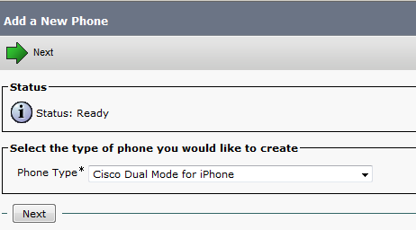
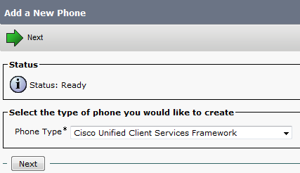
  • Adding a new device
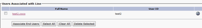
  • Associating a device with a user
  • Assign an Owner for the Phone
  • UCCX Initial Configuration
  • Assign the new Device an IPCC
  • Build Skills & Assign it
  • Assign a Supervisor Capabilities to the user
  • Build CSQ
  • Build Team
  • Build Call Control Group
  • Build Script
  • Upload the script to the IPCC
  • Create a Prompt Folder
  • Add wav file to the prompt folder
  • Create an Application and CTI Route Point
  • Add the Ports to the CTI Admin and the Phones to the RMCM Admin
  • Configure Cisco Unity
  • Configure Transcoder

This post is based on UCCX version 10.0.1 and CUCM version 9.1.2

Lets Start
First in CUCM we build phones
1

Then Create Admin User to use for UCCX Administration Page
3

Then create the Agent and Associate them with the Phone
4

5

6

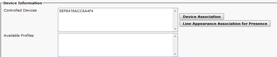
Then we Configure the Owner in the Phone Side
7

Now Lets Start the UCCX Side
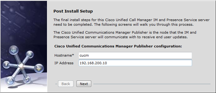
login by the User that been Created During UCCX Installation
8

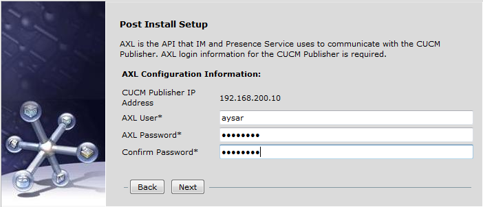
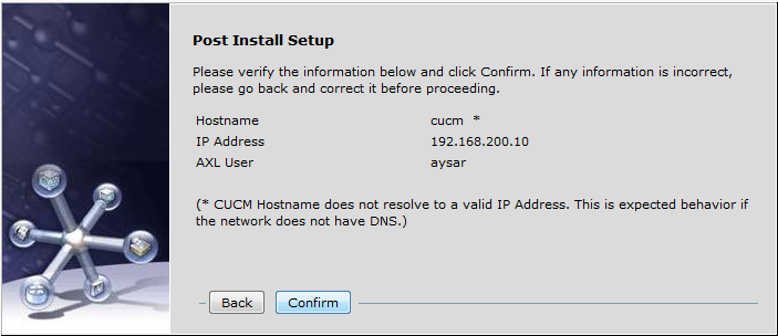
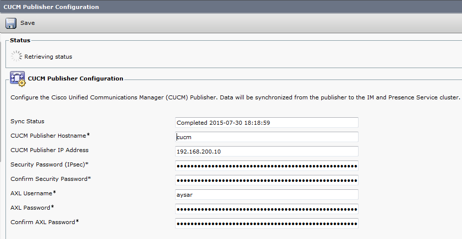
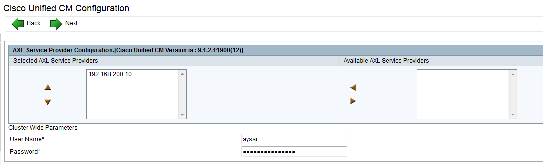
Enter the CUCM IP address and the AXL username & password
9

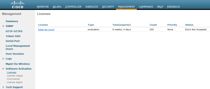
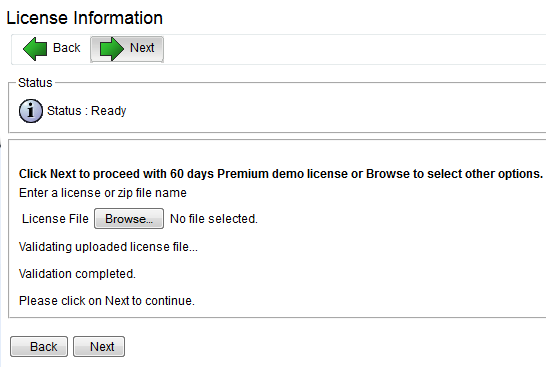
Here we will use the 60 Days Demo
10

11

Then Activate the License Once it activated the next button will highlight
12
Press Next at the second page
14

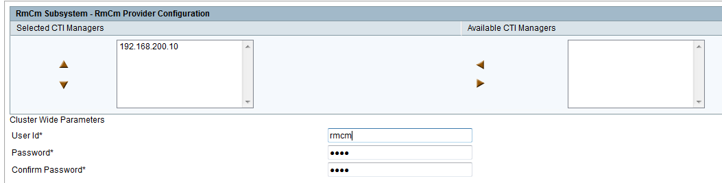
Now Lets Create Username and Password for AXL, CTI Ports and RMCM
15

16

17

Now after that those users will be created automatically in CUCM
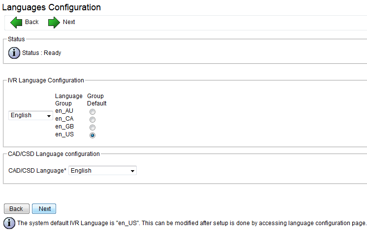
then configure the service Parameter and Language
18

19

That is it it will ask you to install the Cisco Unified CCX Desktop Configuration
20

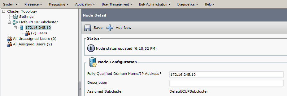
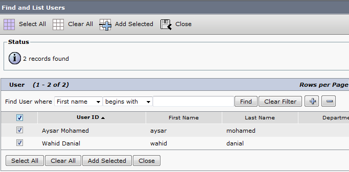
Now Assign the user i create in CUCM which is UCCX as the UCCX Admin
21

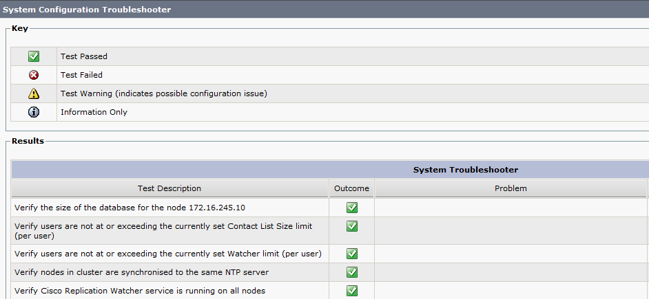
Verification and like this the initial setup is finish
22

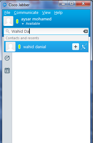
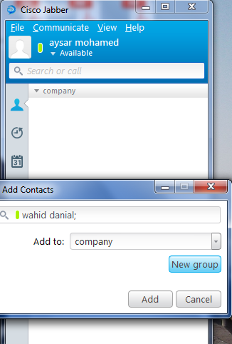
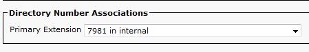
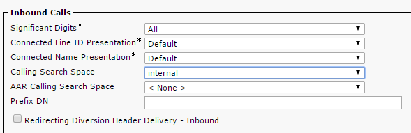
Now Go Back to CUCM and assign to the User an IPCC Extension so you can see the Agent in the resource of UCCX Resource page
23

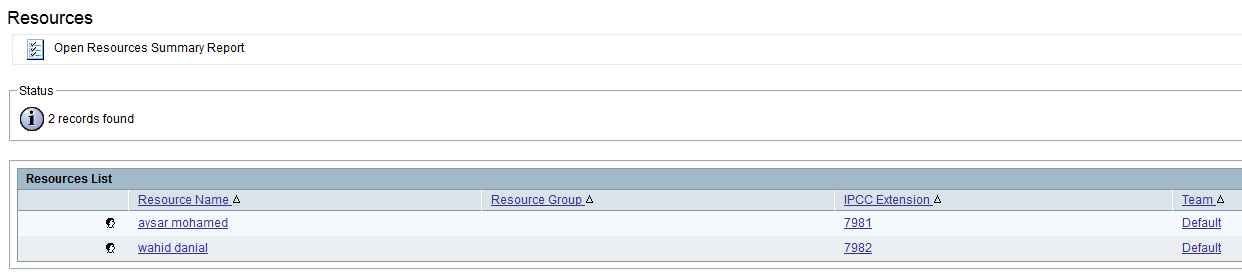
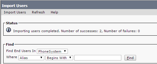
now login to UCCX and go to
Subsystem – RmCm – Resource
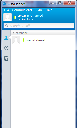
you will see the Agent Sync with CUCM already
25

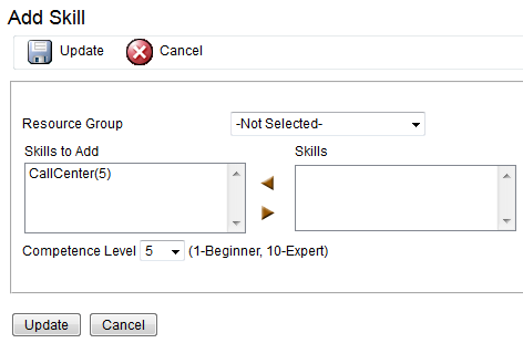
Now Create Skill and Assign it
Subsystem – RmCm – Skills – Add new : Call Center
27

you can go to
Subsystem – RmCm – Resource and Assign it one by one
or
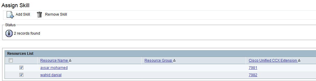
Subsystem – RmCm – Assign Skills to do it all at one
lets go by the second option
29

30
32

Now if you go to the User to check it
Subsystem – RmCm – Resource and select the user you see it already become one f his Skills
33

Now Assign Supervisor Capabilities
Wizard – RmCm Wizard – Add Supervisor
by default all user have agent capability only so all what you need to click on the supervisor and the arrow will move it to the Right Side
36
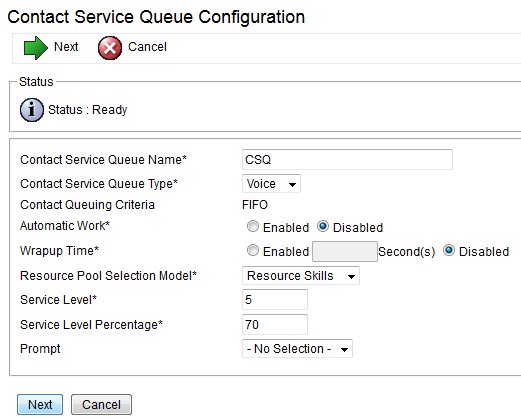
Now Lets Build Contact Service Queues
Subsystem – RmCm – Contact Service Queues
Define the Resource Pool Weather it was by Group or Skill
we will use skills for this option
38

39
by default the Competence is 5 by default you can create your own
i will use the default

Now lets build the Team
Subsystem – RmCm – Teams
1-Assign Supervisour
2-Assign Agent
3-Assign CSQ
41

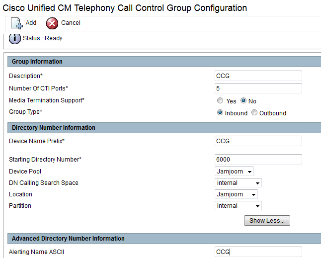
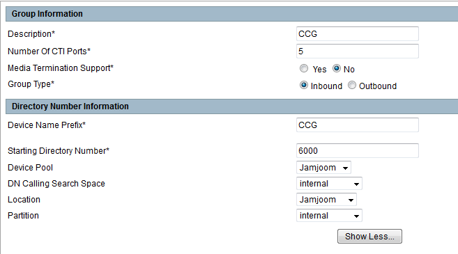
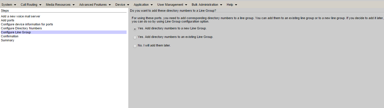
Now Configure Call Control Group
Subsystem – Cisco Unified CM Telephony – Call Control Group
43

44

Now if you go to CUCM you will find the CTI Port has been Created
Device – Phone
45

Now the Big Script
there is a default scrip liberary when you install Cisco Unified CCX Editor which available in C:\Program Files\UCCX Program\Scripts\system\default
our script design to that the agent will recive a call and if they are not available in 30 second the call will forward to the voicemail which include a small configuration in Cisco unity
first login to the software CUCCX Editor which can be downloaded from plugin in uccx web page
1
1

the software will open, i used the default script icd.aef to edit
and there is a small button like an Arrow
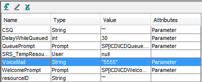
2
called new variable
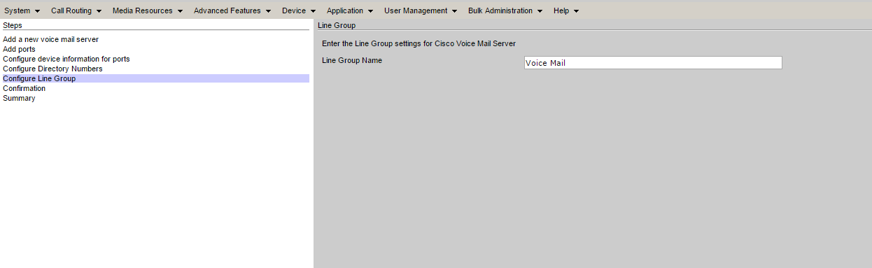
Name the Variable and write the Voice Mail Number that you want to use
in our case we used the name: Voice Mail and the Number : 5555
48

49

then Choose an option to forward the call to Voice Mail once it reach 30 second
the delay is 30 second by default so we only need to add the forward option
50

51

52

53

That is it. now validate the Configuration
Tools – Validate
55

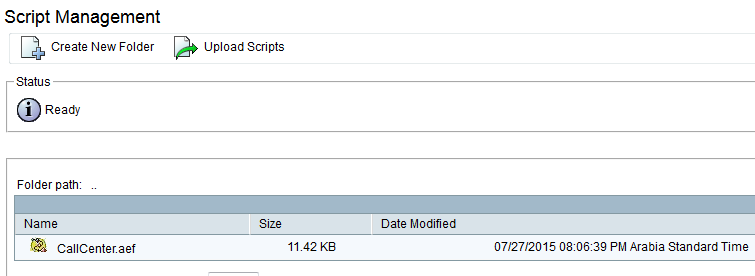
now Save the script to your PC and upload it
Application – Script Management

58

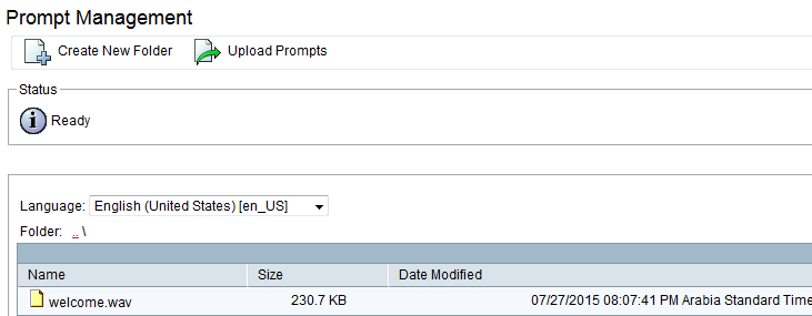
now create a wav welcome message and upload it also to the system
you can create a welcome message by iphone and then convert it in your PC, i use WavPad Sound Editor
Application – Prompt Management – en_US folder then Upload
61

Finally the Application were everything will be collect there and also add a trigger number which is the number will call the whole system
Application – Application Management
63

64

65

66

67
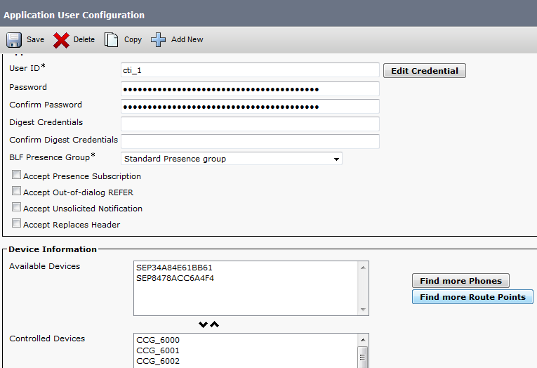
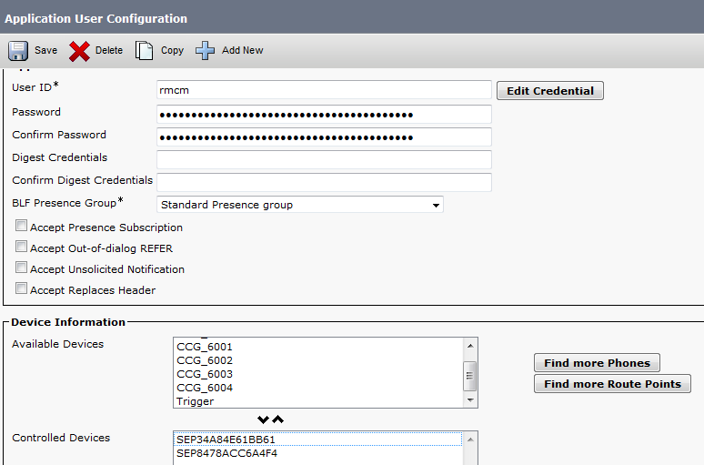
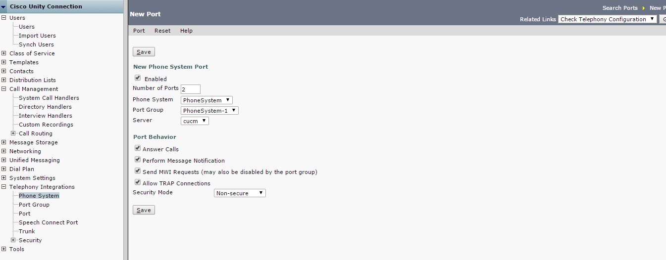
Now go back to CUCM and check the user that been created in the initial Setup in UCCX and assign the CTI Port to the CTI Admin and Associate the phones to RmCm Admin
68

69

Now the Voice Mail Side
in earlier Article i show you how to configure voicemail https://ccieroot.com/2015/07/11/sccp-integratinon-cisco-unity-connection-with-cucm/
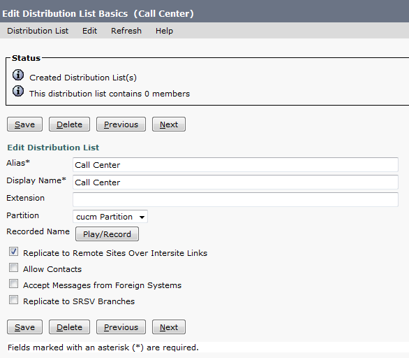
so here i will show you how to create a Distribute List that collect the user of UCCX in one Voicemail inbox so they can check the messages
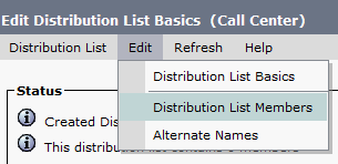
go to Cisco unity connection – Distribute List – System Distribute Lists  Add New
2323

71

72

73

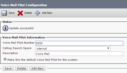
Now Create the Call Handler with the same Variable number that been created in the UCCX which is the Voice Mail Number
in our case is 5555
go to Call Management – System Call Handler – Add new
75

Then after Save go to Edit – Message Settings
change the Message Recipient to Distribute List and choose your Distribute List
77

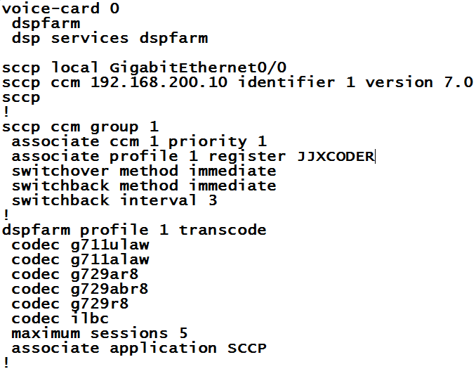
Last thing you need to create a Transcoder since UCCX call will be transferred to CUC
you need to configure it in Router Side and CUCM Side
first configure it in router
78

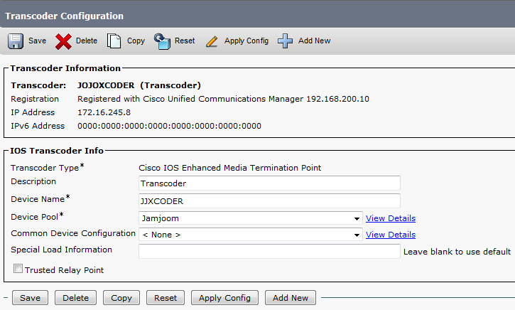
Then go to the CUCM to add it
Media Resources – Transcoder – add it and reset
79

Then Add the Transcoder to a media resource group and a media resource list
Media Resource – Media Resource group
81

Media Resource – Media Resource Group List
83

Now Assign the Media Resource List to the Same Device Pool so it will Transcode the Calls
System – Device Pool
85

And that is it
the System is ready to go
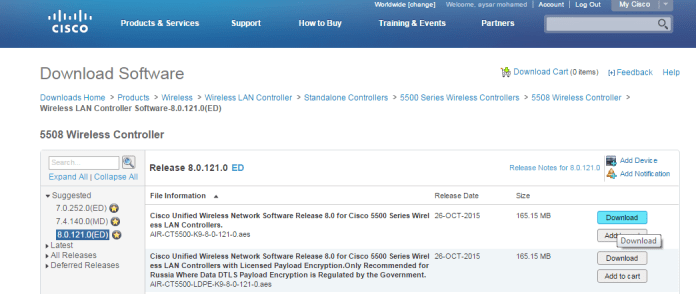
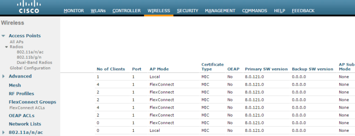
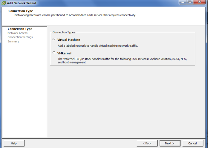
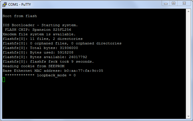
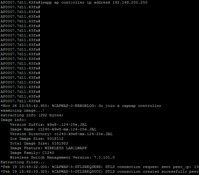
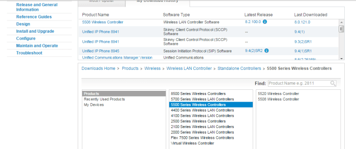
Standard
CUC

SIP Integratinon Cisco Unity Connection with CUCM

In an Earlier tutorial I explain how to integrate CUC with CUCM using SCCP Protocol
https://ccieroot.com/2015/07/11/sccp-integratinon-cisco-unity-connection-with-cucm/

Let’s move to the SIP

First Create Trunk to CUC
Device – Trunk
Configure the DevicePool, Location Incoming CSS,IP Address, SIP Trunk Security Profile & SIP Profile
1

2

3

4

Note: make sure the SIP Trunk Security Profile has the following settings are selected;

  • Accept Out-of-Dialog REFER
  • Accept unsolicited notification
  • Accept replaces header

Second Create a Route Pattern toward the Voice Mail Number which is 5555 in our case
Call Routing – Route/Hunt – Route Pattern
Choose a partition and the SIP Trunk that you just create

5
Next Step is to configure a Voice Mail Pilot and Voice Mail Profile
6

7

Last step is to configure MWI in service Parameter
System – Service Parameter – Choose the Call Manager Server – Call Manager
and Enable the Service Multiple Tenant MWI Modes
8
Now We Finish the CUCM Part let’s Move to the CUC
First Add the CUCM AXL Server which usable to import the Users from CUCM
13-A

2

Then From Right Corner we chose to add Port Group
here you Decide which protocol you are using weather its SIP or SCCP
in this scenario i choose the SIP
Notice there is no option for Prefix Name like SCCP or MWI Cause SIP use SIP-Notify not MWI Dn

4

5

Then Configure The Ports
7

From Right Side Corner we can check the telephony to make sure no problem exist in the System

8
now time to import the users

The only last thing is to import user from CUCM
go to Users – Import User
Select Import All or By Choose which user you want to have a Voice Mail
all 1

all 2

all 3
Change their Active Schedule to all hour is a better choice and Change their Password
all 4

all 5
and now you can test your Calls to the VM Pilot Number or press the envelop Button

Standard
CUC

SCCP Integratinon Cisco Unity Connection with CUCM

Long Time No See and Finally im back ;D

In this tutorial, i want to give you an overview what has to be done and configured to integrate Cisco Unity Connection 9 with CUCM 9.
Unity Connection can be integrated with CUCM using 2 methods, SCCP or SIP, the differences and similarities are detailed below:

SIP Integration

  • Requires a SIP Trunk pointing to Unity Connection
  • Requires a route pattern to send calls to the SIP trunk
  • Does not require MWI DNs, uses SIP NOTIFY messages

SCCP Integration

  • Requires SCCP Ports, along with Line Group, Hunt List & Hunt Pilot
  • Dedicated DNs for MWI on/off

Both integrations require a VM Pilot and a VM Profile.

i will start by the SCCP in this tutorial

at an earlier tutorial i show you how to configure CUCM to make calls
https://ccieroot.com/2014/11/08/cisco-unified-communications-manager-cucm-initial-setup/

After that we start the integration
First we create the Voice Mail Port
Advanced Featured – Voice Mail – Cisco Voice Mail Port Wizard
Give it a name
1
Then Choose the number of the Ports
2
Now Choose Description and Device Pool And CSS and the most important the Security Mode
3
Now Choose the Beginning Directory Number and Which Partition and CSS it will Contain
4
After this add it to a Hunt Group which contain the Voice Mail Port
5

6
Verification show in the next screen
7
Now it show the Final Result
8
Now i need to Add it to a Hunt List and Configure a Hunt Pilot Number in Our Case its 5555
9

10

Now Configure my MWI (Message Waiting Indicator) On & Off
11

12
last two thing is the VOice Mail Pilot and Voice Mail Porfile
Voice Mail Pilot

Voice Mail Profile
Now We Finish the CUCM Part let’s Move to the CUC
First Add the CUCM AXL Server which usable to import the Users from CUCM
13-A

13-B

Then From Right Corner we chose to add Port Group
here you Decide which protocol you are using weather SCCP or SIP
in this scenario i choose the SCCP
be careful about the Device Name Prefix it should be the same you choose in CUCM Part which in our case is (CiscoUM1-VI) you can find it under Voice Mail Ports dont put the number next to the name
and Add the CUCM ip address and MWI
1

13
Second We Add Port to it
we choose the same number that you choose in CUCM part which is 2
14

Done
The only last thing is to import user from CUCM
go to Users – Import User
Select Import All or By Choose which user you want to have a Voice Mail
all 1

all 2

all 3
Change their Active Schedule to all hour is a better choice and Change their Password
all 4

all 5
and now you can test your Calls to the VM Pilot Number or press the envelop Button

Standard
Uncategorized

Implementing SIP Gateways in CUCM

I been Requested to make a blog about SIP Implementation by a Big Company in Saudi Arabia which make me proud just to post this here so let me start by explaining ;D

To place external calls, Cisco Unified Communications Network (CUCM) deployment needs a connection the Public Switched Telephone Network (PSTN). Gateways can be integrated in CUCM by using different protocols such as Media Gateway Control Protocol (MGCP), H.323 or Session Initiation Protocol (SIP) for signaling on VOIP call legs.
In an Earlier Blog i show you how to Configure the CUCM and make Calls through an H.323 Gateway which an earlier technology https://ccieroot.com/2014/11/08/cisco-unified-communications-manager-cucm-initial-setup/

In this blog i will show you how to configure a SIP Gateway in CUCM and in the IOS so First Make Sure you have all your Information about the Numbering Range and the SIP Server with you so no Delay could happen in configuring your Site
in our example our Numbering Range is 2217910 to 2217919
and the SIP Server is  10.208.9.69
My Gateway IP is 172.29.7.94

in the CUCM go to Device – Trunk – Add New SIP Trunk and Device Protocol as SIP and None for Trunk Service Type
Name the Device anything you want and choose the correct Device Pool, Location and configure your Calling Search Space for inbound Call Then go down Type the Address of your Gateway n the Field of Destination Address in our case 192.168.200.86, Chose your SIP Trunk Security Profile and SIP Profile

Screenshot 2014-11-08 17.58.45


Screenshot 2014-11-08 17.58.49


Screenshot 2014-11-08 17.58.53


Now Configure the Dial Peer for the SIP in the CUCM
something you should make sure from is when you make a call to outside number that your the calling number which is your ID number is the 221791X not only 791X  cause then it will drop your call
so you have two option weather you make a translation rule or prefix the 221 in the dial-peer
in our example we prefix it in the dial peer
so Go to Call Routing – Route/Hunt – Route Pattern – Add New
we will configure a route pattern to a mobile Number so you choose the Route Pattern which is 9.05XXXXXXXX, Choose the Route Partition and the Gateway/Route List. Afcors click the Provide Outside Dial Tone and change the Call Classification to Offnet
and here is the extra thing that differ this from H.323 configuration which is the
Calling Party Transformations we add  to Prefix Digits (Outgoing Calls) 221

1


Now Let’s Configure the IOS

First let me configure my Interfaces

interface GigabitEthernet0/0
Description “Lan Connection”
ip address 192.168.200.86 255.255.255.0
duplex auto
speed auto
!
interface GigabitEthernet0/1
ip address 172.29.7.94 255.255.255.252
duplex auto
speed auto

Then Enable the route to the SIP Server

ip route 10.208.9.0 255.255.255.0 172.29.7.93

Now lets enable the voice service and allow it to communicate with different protocol

voice service voip
allow-connections h323 to h323
allow-connections h323 to sip
allow-connections sip to h323
allow-connections sip to sip
sip
early-offer forced

“early-offer forced” it allows SIP Gateway to route calls in a Delayed Offer to Early Offer scenario. Almost all of the providers require Early Offer SIP calls. It is actually recommended to send Early Offer from CUCM in order to avoid early media cut-through issues.

Now Configure the Translation rule for outgoing call
voice translation-rule 1
rule 1 /^9\(\)/ /\1/

Added to a translation Profile
voice translation-profile OUT
translate called 1

and then added to a dial-peer
dial-peer voice 700 voip
description ** SIP TO STC **
translation-profile outgoing OUT
destination-pattern 9T
session protocol sipv2
session target ipv4:10.208.9.69:5060
session transport udp
voice-class sip dtmf-relay force rtp-nte
dtmf-relay sip-notify rtp-nte sip-kpml
codec g711alaw

the Command
voice-class sip dtmf-relay force rtp-nte
dtmf-relay sip-notify rtp-nte sip-kpml
is optional you could have enouhg by using
dtmf-relay rtp-nte sip-notify
but i use it all for worse cases

and Since our Phone Extension is 4 digit only we need to make a translation rule that strip the Number from the 221 for incoming call

voice translation-rule 2
rule 1 /^2217/ /7/
rule 2 /^0122217/ /7/

and added to a translation profile
voice translation-profile SIP-IN
translate called 2

and then configure an Incoming Dial-peer
dial-peer voice 701 voip
translation-profile incoming SIP-IN
destination-pattern 791.
session protocol sipv2
session target ipv4:192.168.200.10
incoming called-number 012221791.$
dtmf-relay sip-notify rtp-nte sip-kpml
codec g711alaw

Also the Command
incoming called-number 012221791.$
is optional now you can use
incoming called-number .
or nothing at all the call will use the destination-pattern to reach the phone but i use it for worse cases

Now you can try to make a call and it will go through


Standard
Uncategorized

Cisco Unified Communications Manager (CUCM) Make It Work

I have created a blog before about the installation of the CUCM https://ccieroot.com/2014/10/24/installation-of-cucm-8-6/ but after that you need to complete couple of steps to make your cucm run like a charm and all of your phone able to call Each Other in the network so lets start

the first step which is optional is to change the server name to an IP Address in case you dnt have a DNS and change the timing of the Server

Go to System – Server – press Find and change the name to an IP

Screenshot 2014-11-08 16.28.23


Screenshot 2014-11-08 16.28.35


Go to System – Date/Time Group and then Save and Reset

Screenshot 2014-11-08 16.45.10


Second thing is the region which is configure by default, you can create a new one but in our case we will leave it as its
From System – Region Information – Region
Screenshot 2014-11-08 16.29.08


Third step is the Location which also configure by default which we will use
Go to System – Location info – Location
Screenshot 2014-11-08 16.30.19


Now the Biggest thing is the Device Pool which hold all this information together
Go to System – Device Pool and there is one configured by Default and configured with the CUCM Group and Region and the Timing you just need to add the Location to it
Screenshot 2014-11-08 16.46.51


Now go to Call Routing – Class Of Control – Partition – Add New

since this blog only about the initial Step after Installation of CUCM i will not explain the partition and CSS but i will show you how to configure it
Screenshot 2014-11-08 16.31.45


Save it and now Go to Call Routing – Class Of Control – Calling Search Space and configure the partition under each CSS that belong to
for Ex. Internal CSS only have internal partition which mean he can call people under internal Partition
Local CSS can call Internall Partition and also Local Partition…etc

Screenshot 2014-11-08 16.32.13


Screenshot 2014-11-08 16.32.21


Screenshot 2014-11-08 16.32.29


Screenshot 2014-11-08 16.32.37


Now we Configure the phones go to Device – Phone – Add New

Choose the Model of the phone and the protocol
in our case cisco ip phohne 8941 and protocol SCCP
Insert the MAC Address, choose Device Pool, Phone Button Template, Softkey Template,Location and for Owner Option Make it Anonymous and last select the Device Security Profile
1


2


Save and then go to the Left Side to add the Extension go to Line1 Press on it
Choose the Extension you want, in our case we put 7912 and we put it under partition Internal then i give name for the Alerting Name and ASCII Alerting Name and choose a Calling Search Space which we make it a mobile which mean he can call people in internal, local and mobile partition.
and then i configure the name in the field of Display (Caller ID), ASCII Display (Caller ID), Line Text Label and ASCII Line Text Label
1


2


Now Configure all your phone the same way with Different Directory Number and Like That all your employee can call each other and like that your CUCM is Ready
The next step is to configure the Gateway and Weather it was H.323 or SIP so you can be able to make an outside call, in our example we will configure an H.323
Go to Device – Gateway – Add New – Choose H.323 Gateway and Press Next it will take you to the page of the Gateway and you need to configure most important is the Device Name which is the IP Address of the Gateway, Device Pool, Location and configure Calling Search Space for Inbound Call when it come to your Port in our Case “Internal”. After you save you have to Reset so the Gateway Will Register to the CUCM

1


2


Now We Configure a Route Pattern so Go to Call Routing – Route/Hunt – Route Pattern – Add New
we will configure a route pattern to a mobile Number so you choose the Route Pattern which is 9.05XXXXXXXX, Choose the Route Partition and the Gateway/Route List. Afcors click the Provide Outside Dial Tone and change the Call Classification to Offnet

1


OMG this is the Longest Blog i ever write but don’t worry
Now this the Last thing to DO is to configure the IOS Gateway
First enable the voice service and allow it to communicate with different protocol

voice service voip
allow-connections h323 to h323
allow-connections h323 to sip
allow-connections sip to h323
allow-connections sip to sip

Then Go Under Each Port and Trunk all of them Under one Trunk Group and also configure that when ever a call come it will go to a specific directory number for example the Reception or the Attendant System … for this example i choose the Reception DN which is 7912

voice-port 0/2/0
trunk-group AYSAR
connection plar opx 7912
!
voice-port 0/2/1
trunk-group AYSAR
connection plar opx 7912

Now Configure the outpound Dial Peer

dial-peer voice 1 pots
trunkgroup AYSAR
description “Mobile Call”
destination-pattern 905……..
forward-digits 10

or

dial-peer voice 1 pots
trunkgroup AYSAR
description “Call Anywhere”
destination-pattern 9T
“This Call the Lazy 9 instead of Configure a dial peer for different Route Pattern (Local, Mobile, international) we just have this one dial peer for all”

and configure an Inbound Dial Peer for incoming Call

dial-peer voice 3000 voip
destination-pattern 791.
session target ipv4:192.168.200.10
dtmf-relay cisco-rtp rtp-nte h245-alphanumeric
codec g711alaw
no vad

Now Try to make a call and it will work and call your company and your phone will work
test it in your environment or lab and if you have any Doubt or didn’t work just ask me

The END

Standard